Assembly
IMU (Inertial Measurement Unit)
Section titled “IMU (Inertial Measurement Unit)”This guide is using the LSM6DSV IMU from Mofflab
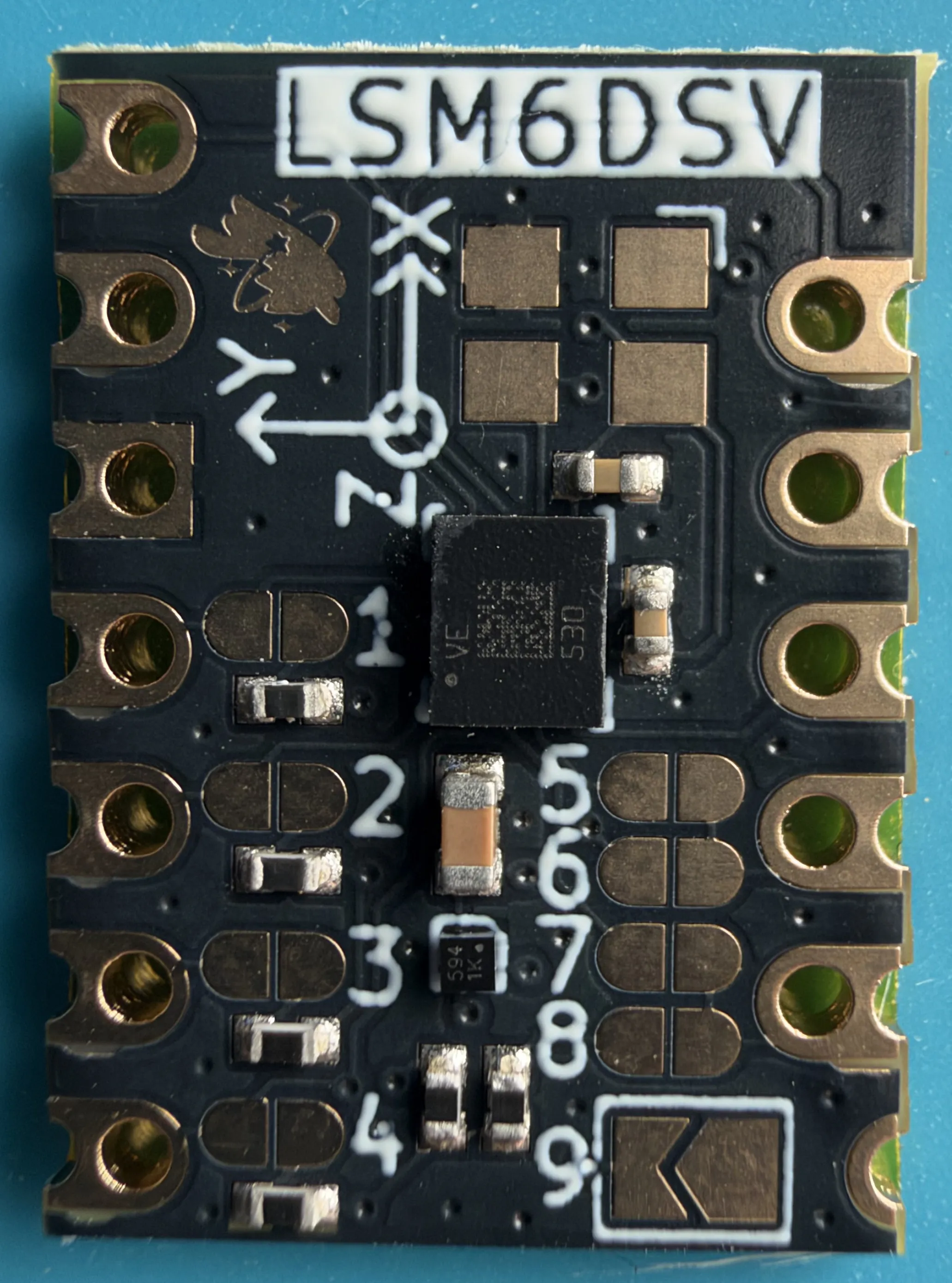
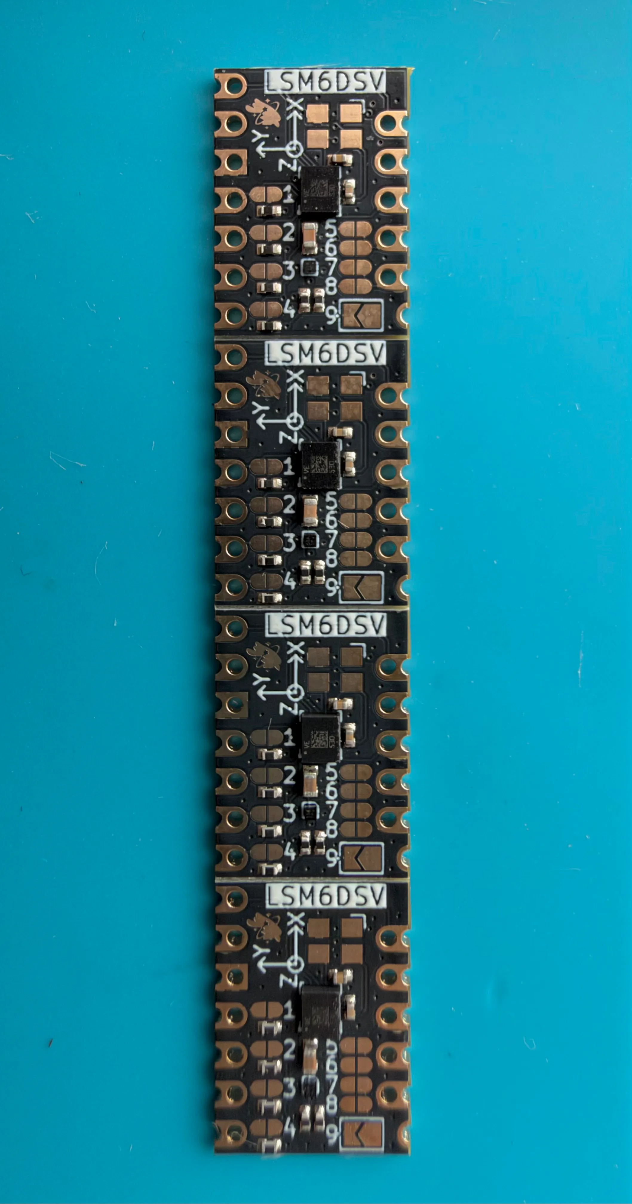
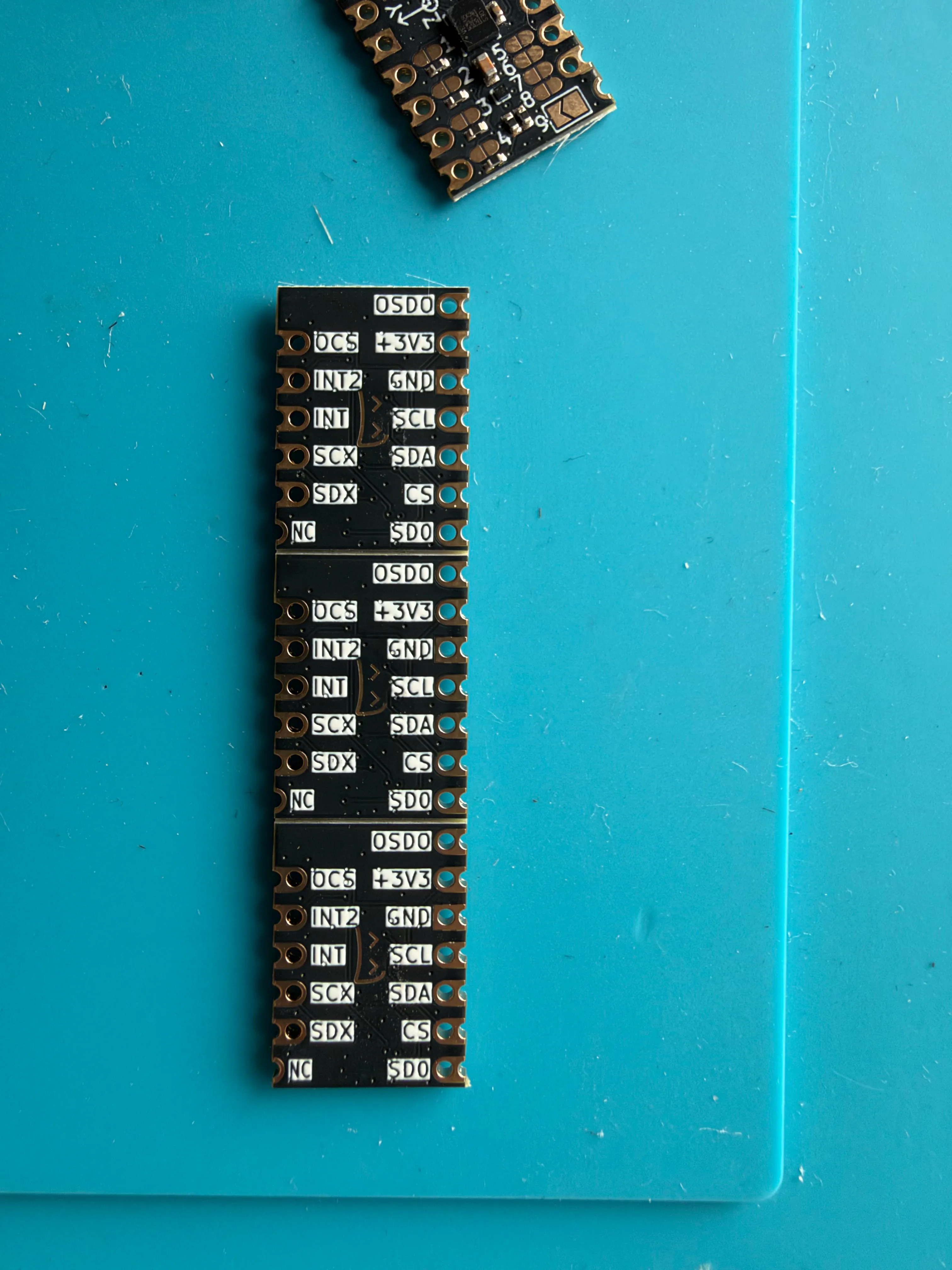
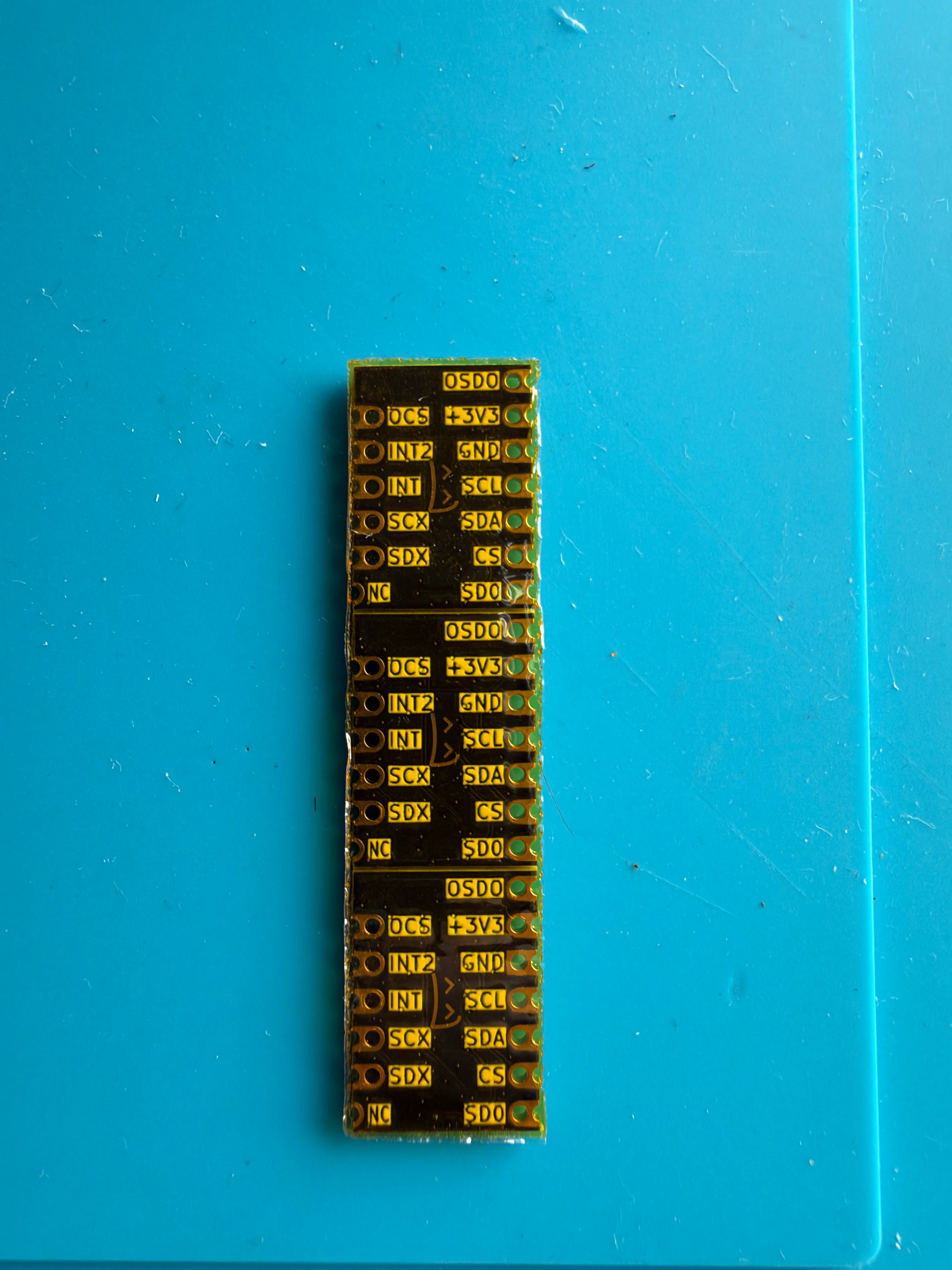
When your IMUs arrive assuming they are LSM6DSVs ordered from Mofflab they will arrive connected like the following:
 |  |
Protective Taping
Section titled “Protective Taping”Applying tape
Section titled “Applying tape”To protect the IMU that will be tightly stacked on top of the rest of our electronics we want to apply Kapton Tape to the back of the IMU to ensure that no contacts are shorted against the board underneath it
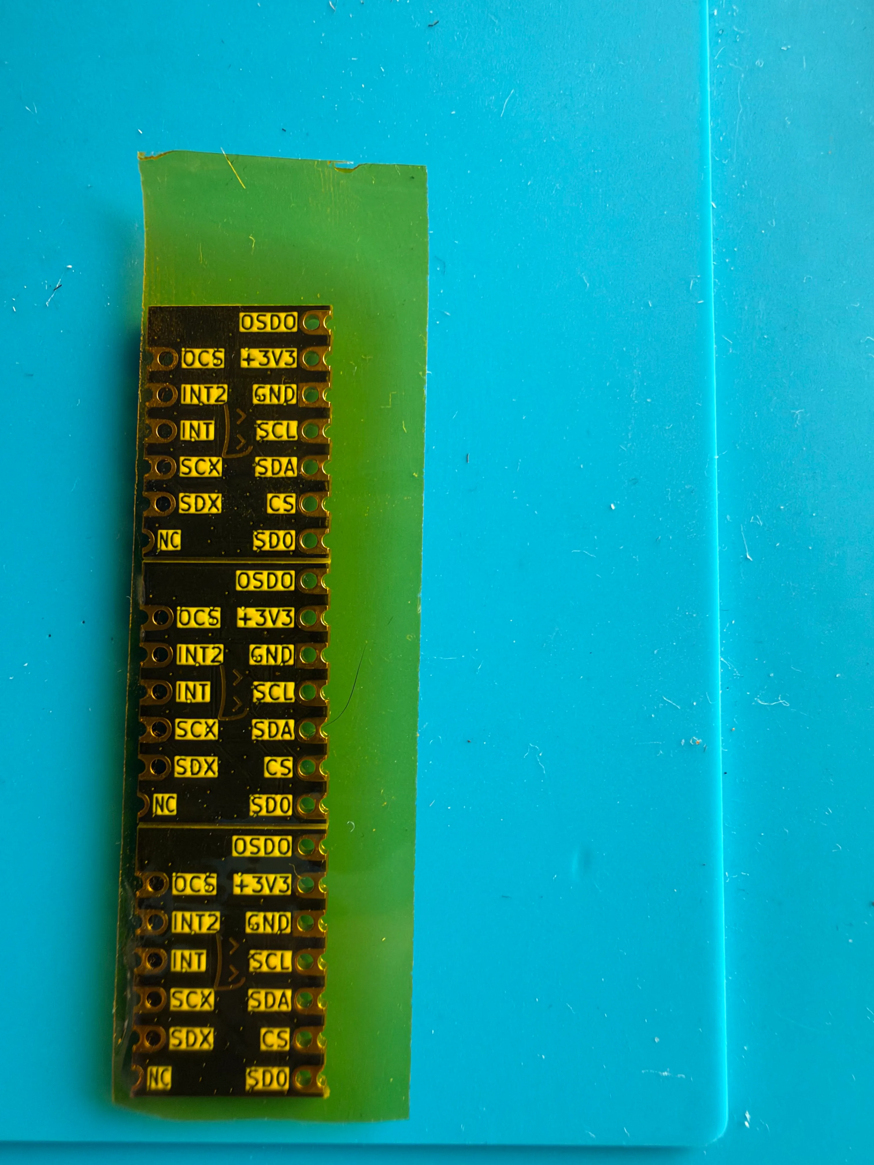
Trimming down the tape
Section titled “Trimming down the tape”After applying your tape trim down the tape with scissors or a sharp craft knife so that it matches the size of the IMUs
Splitting IMUs
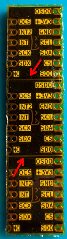
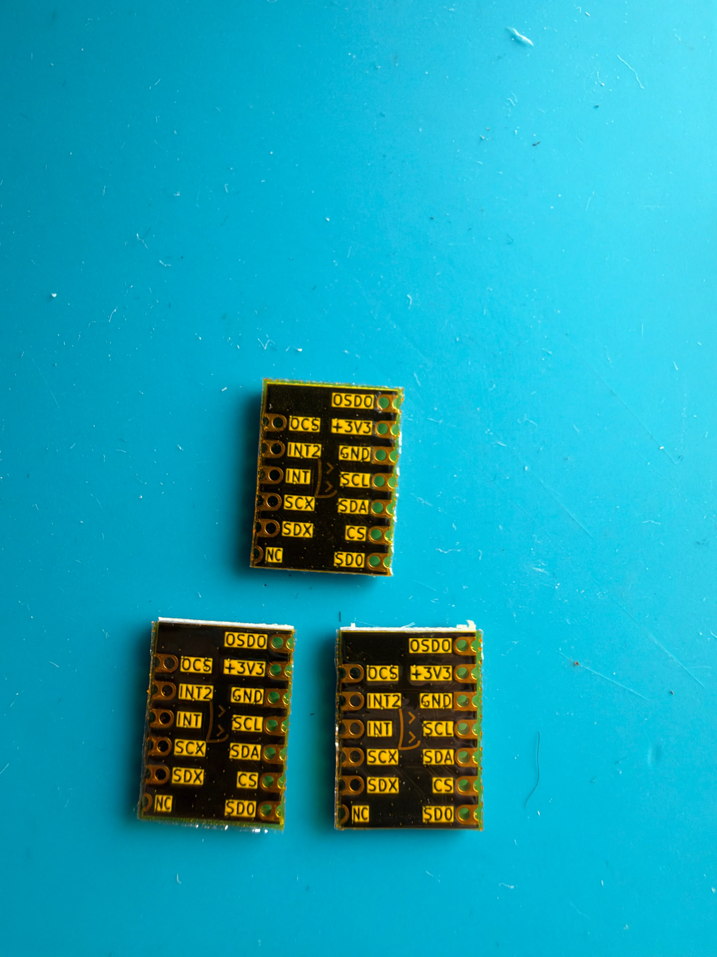
Section titled “Splitting IMUs”Now that you’ve taped your IMUs you can split them apart, I recommend running a sharp knife across the dividing lines to split the tape and loosen then bond before gently bending until it snaps off
 |  |
Magnetometer soldering
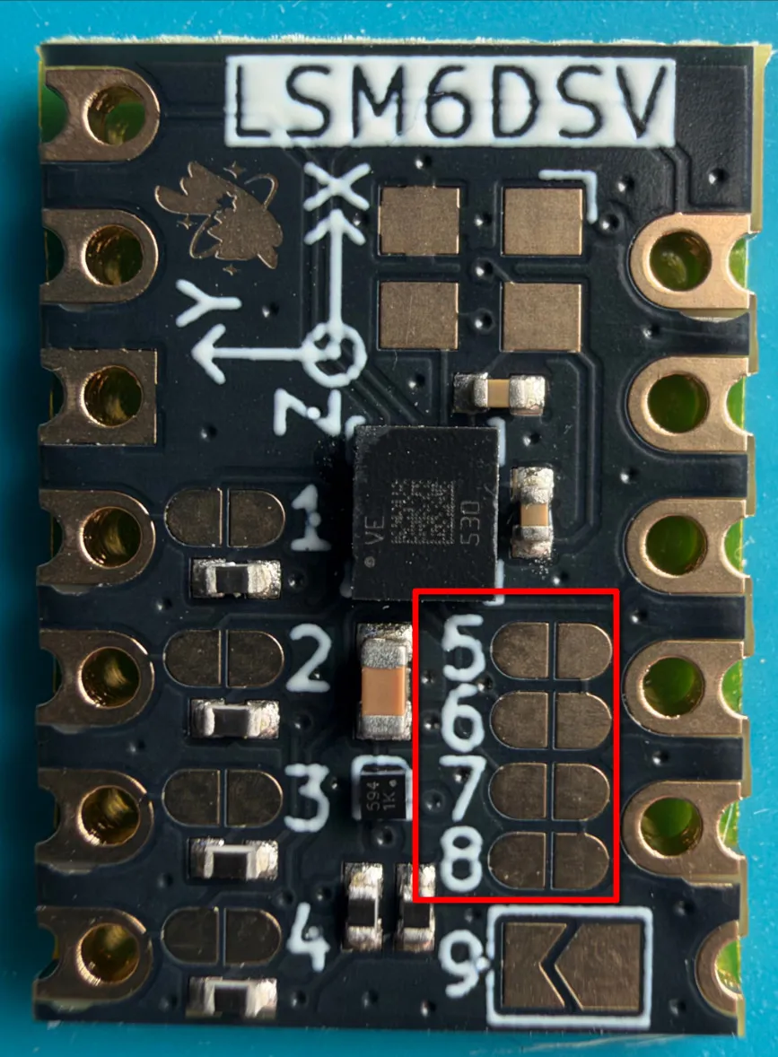
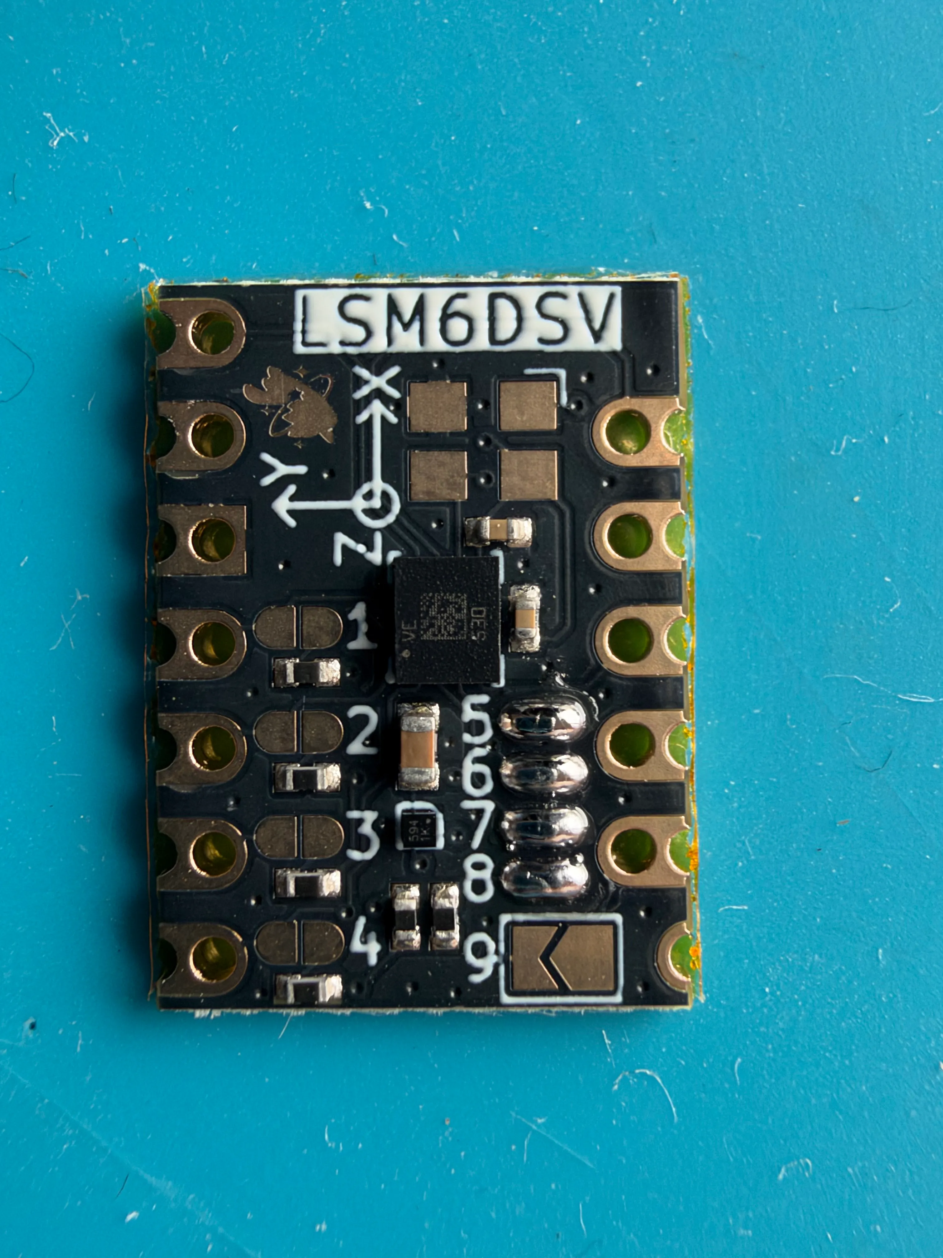
Section titled “Magnetometer soldering”The LSM6DSV chip has its magnetometer disabled out of the box through jumper pins, if you plan on using them you will need to connect these pins. If you don’t want to use the magnetometer you can skip this step.
To connect the magnetometer you must bridge pads 5, 6, 7, and 8 like so:
 |  |
Pre-Soldering the IMU
Section titled “Pre-Soldering the IMU”This step has been designed by ibis-trackers to avoid damaging other components when connecting your IMU. This step uses the Soldering Cube model to assist with aligning and soldering pins.
Preparing Pins
Section titled “Preparing Pins”Your MCU board should have come with set of pins, we will be using these to connect our MCU and IMU together.
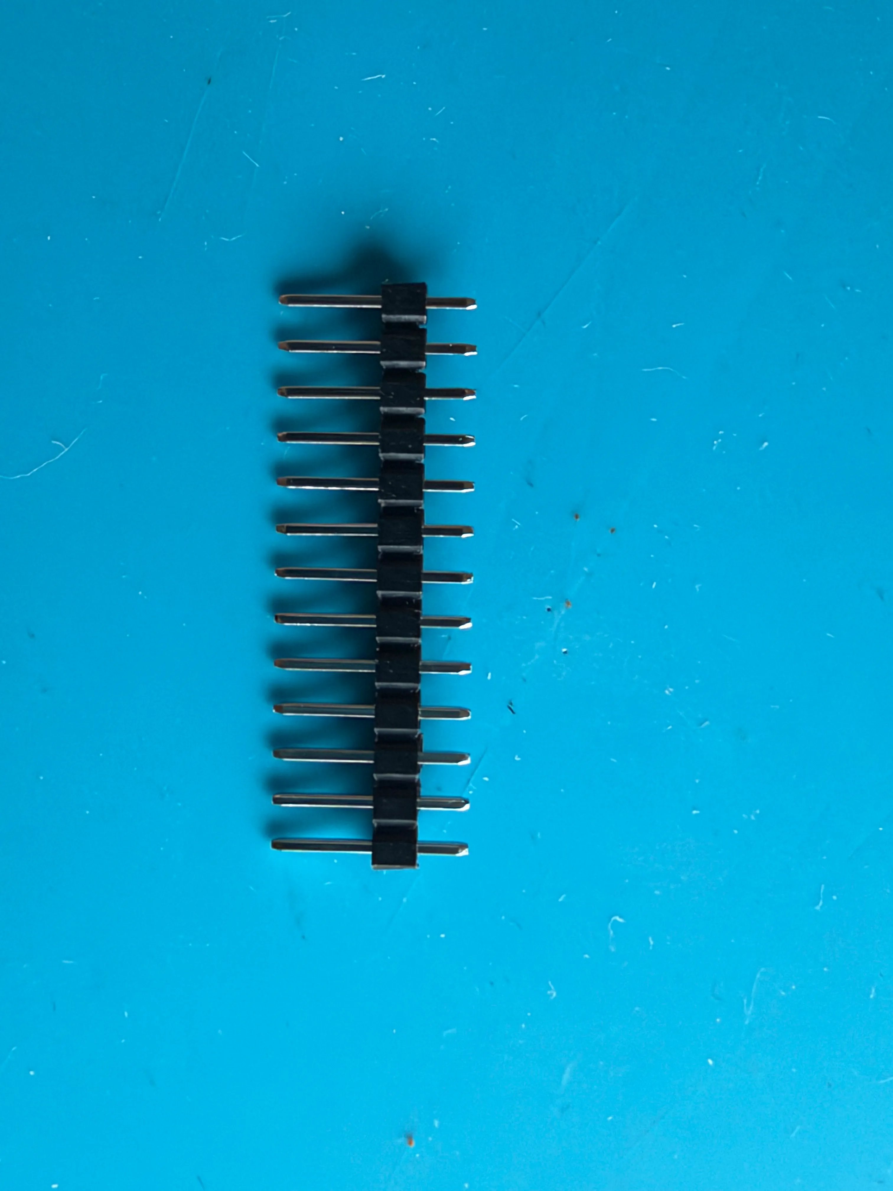
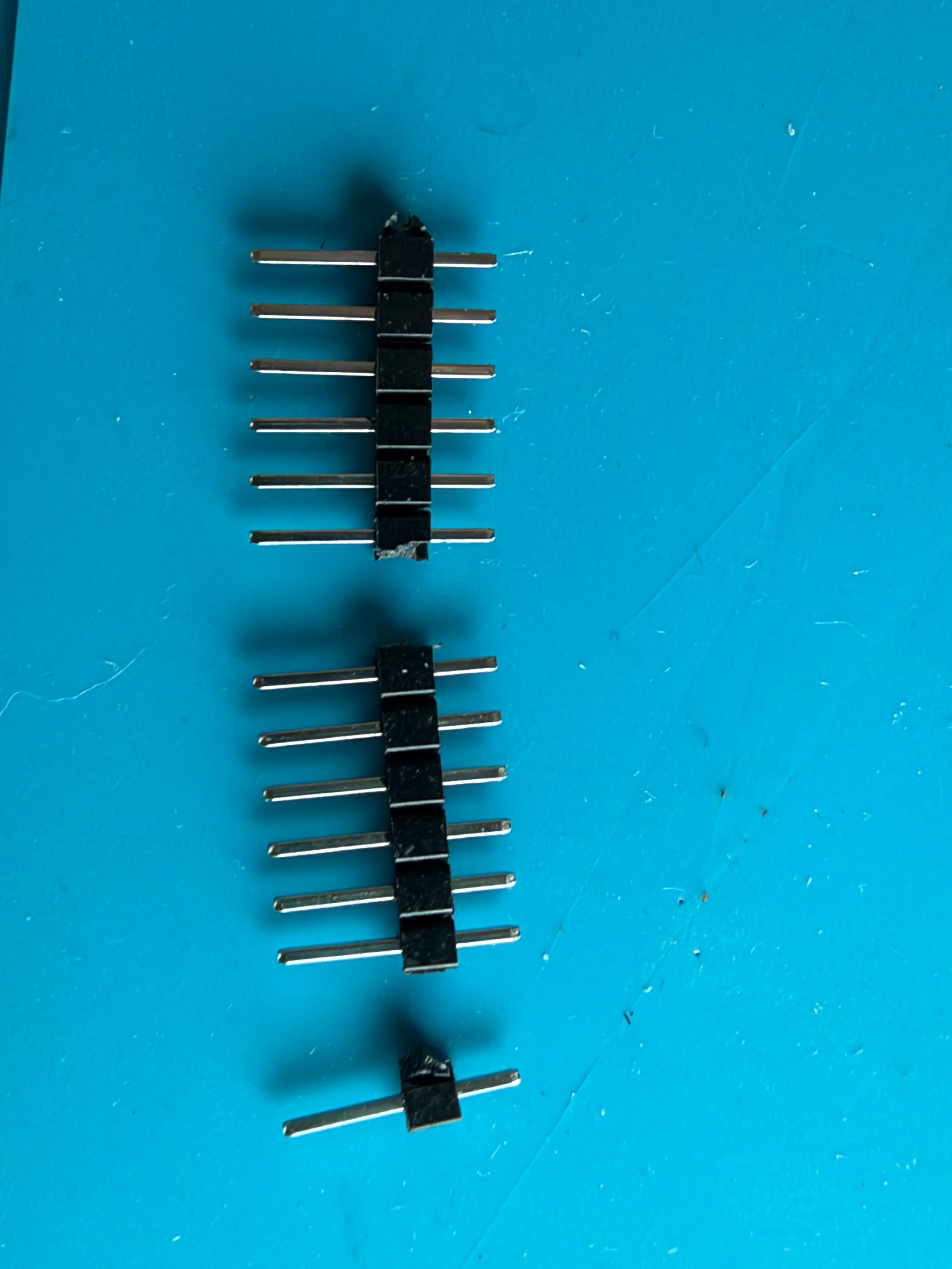
Take your pins and split them into 6 + 6 + 1 (Each row should have 13 pins) like so:
 |  |
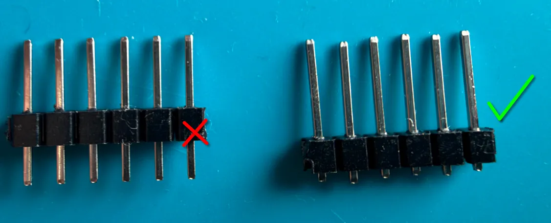
Once you’ve split the pins you’ll need to push down the plastic covering till the pin is barely sticking out the bottom like so:
Preparing your solder cube
Section titled “Preparing your solder cube”First place your IMU in the top of the soldering cube, the side with the most pins should be facing outwards towards the open side of the cube like so:
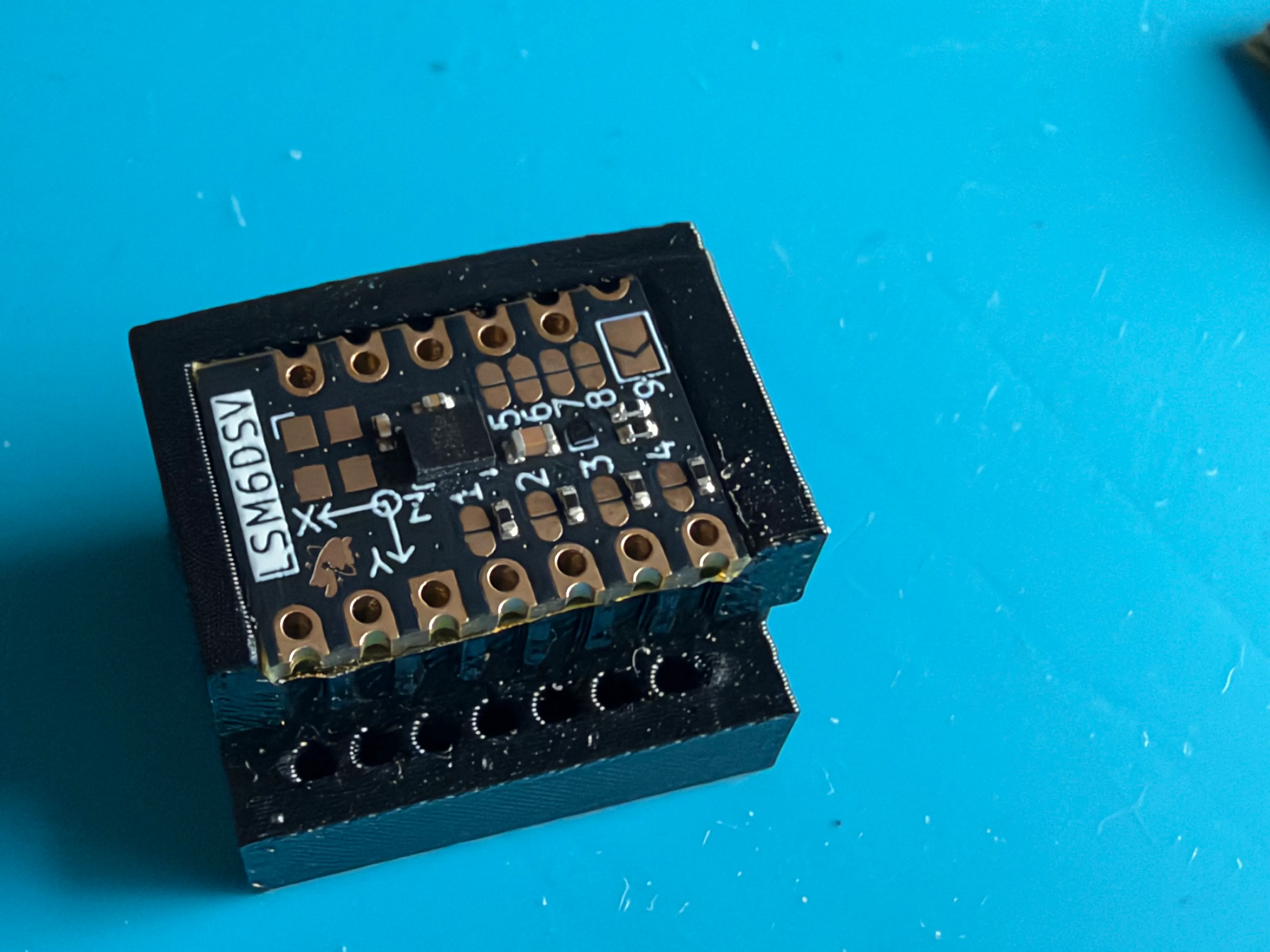
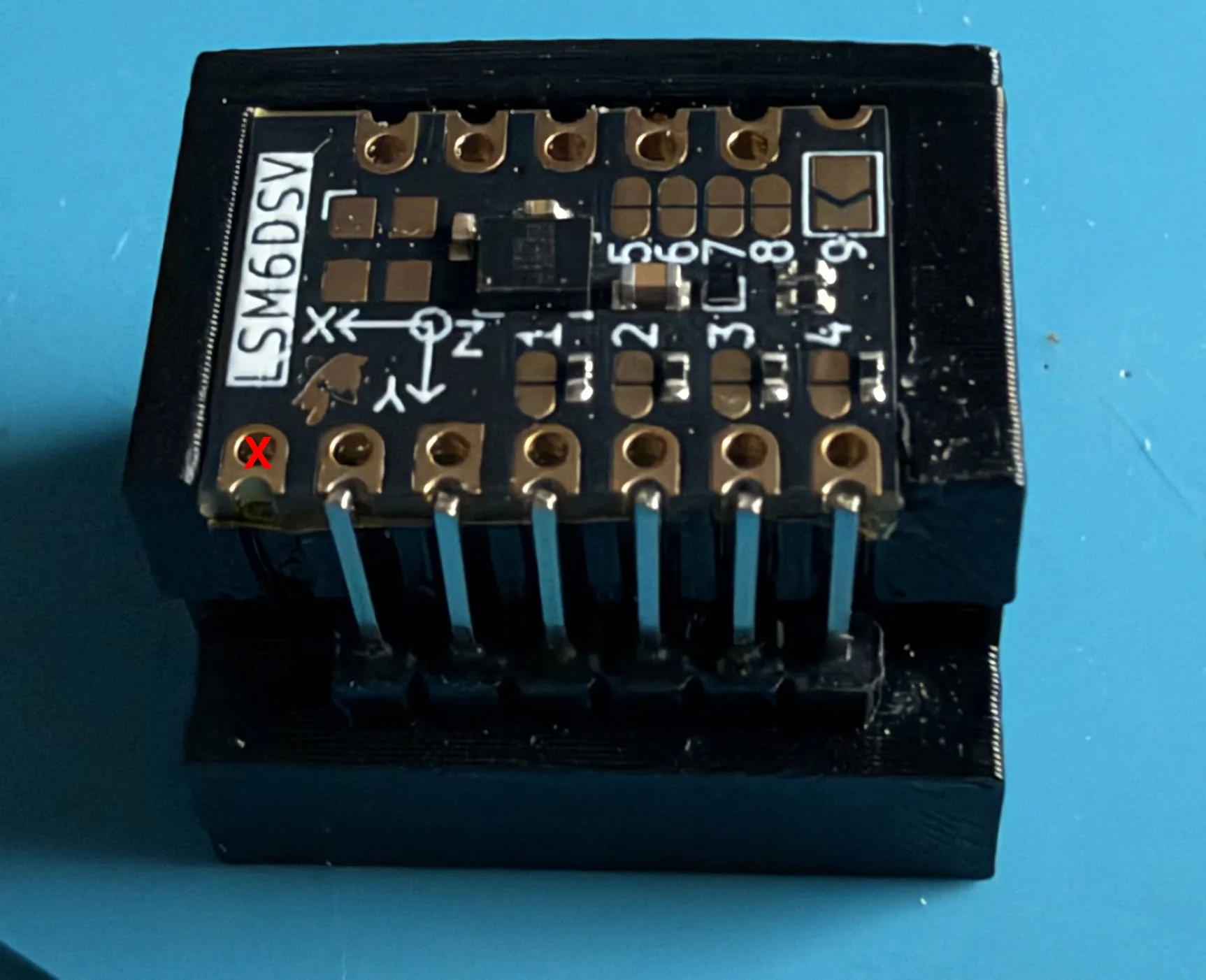
Next place the pins you cut so that they sit in the following holes on the soldering cube, the pins should line up with the outer slits on the IMU DO NOT place them through the holes on the IMU.
Only the last 6 pins should line up, skip the first pin on the left:
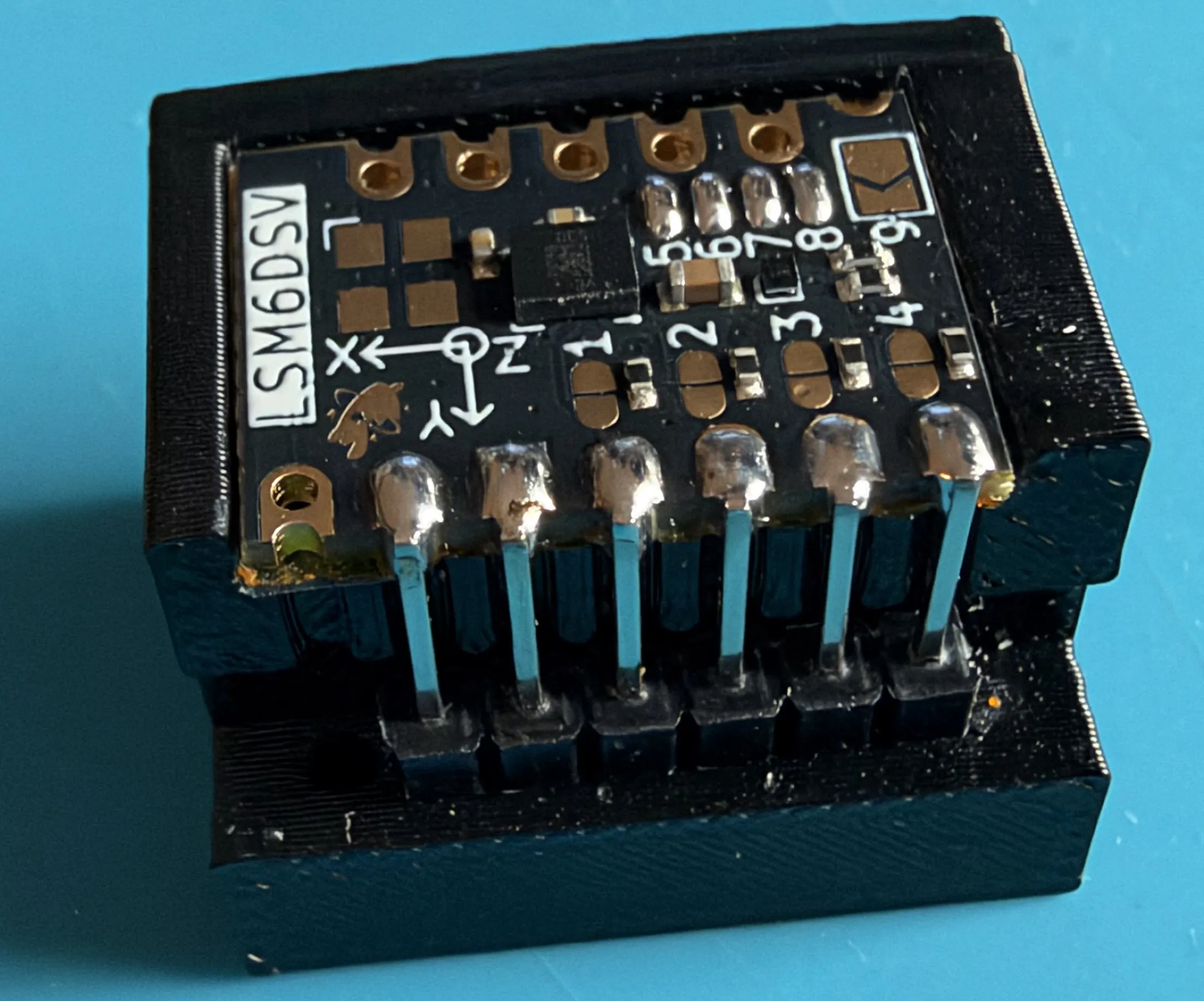
Solder the pins
Section titled “Solder the pins”You can now solder the pins to the pads on the IMU:
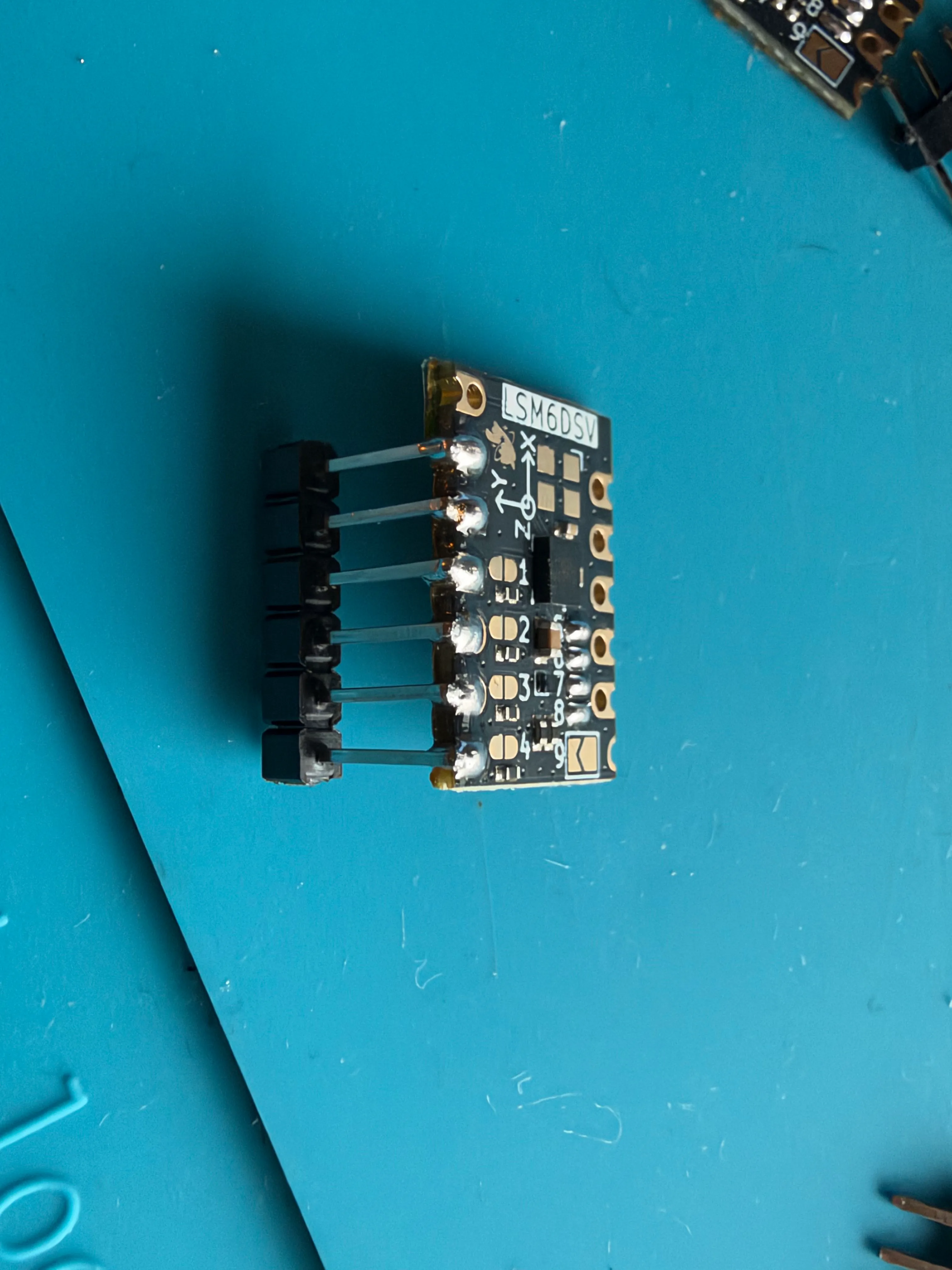
Remove the IMU from the soldering cube
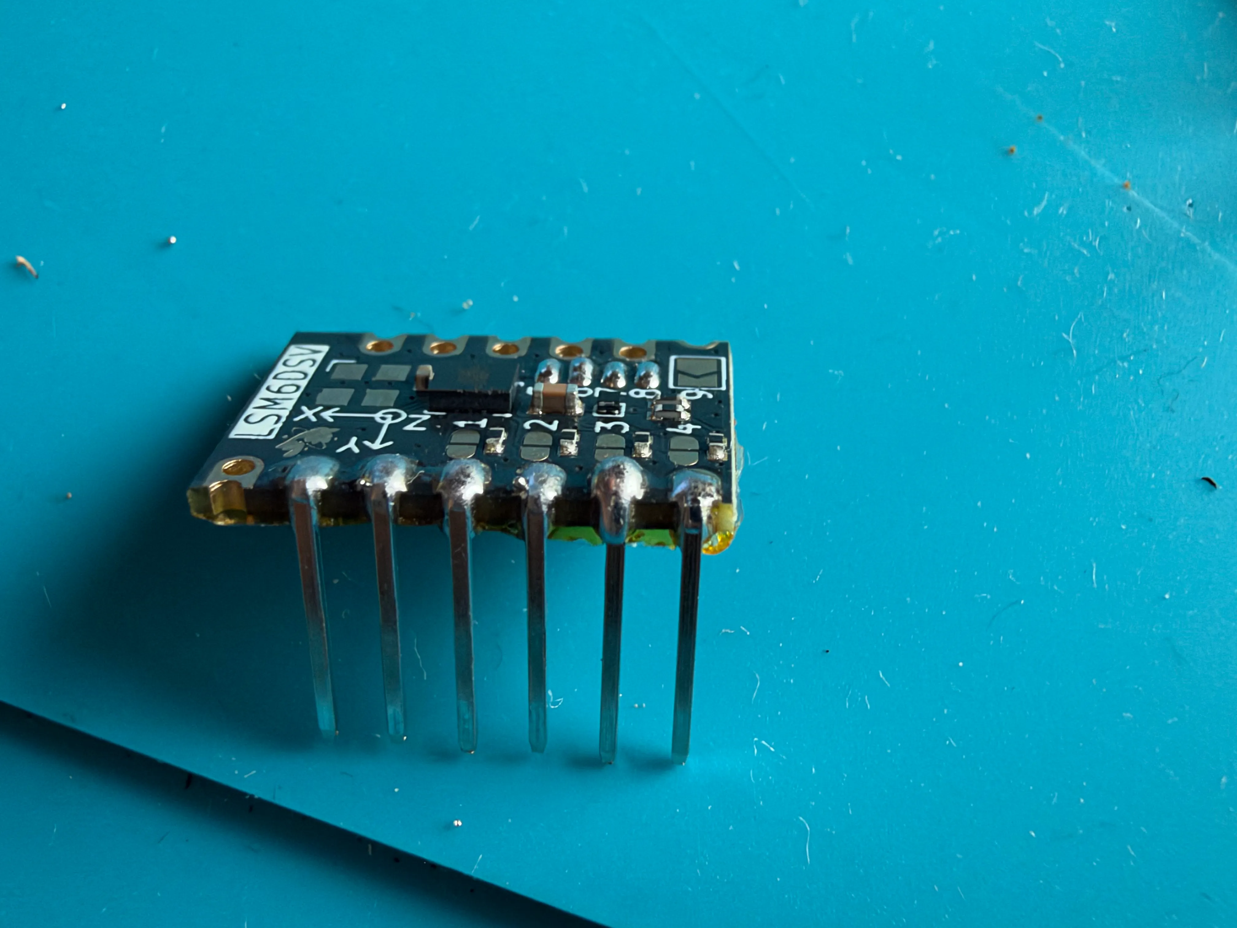
Section titled “Remove the IMU from the soldering cube”Now that you’ve finished soldering the IMU you can remove it from the soldering cube and remove the plastic casing from the pins:
 |  |
MCU (Microcontroller Unit)
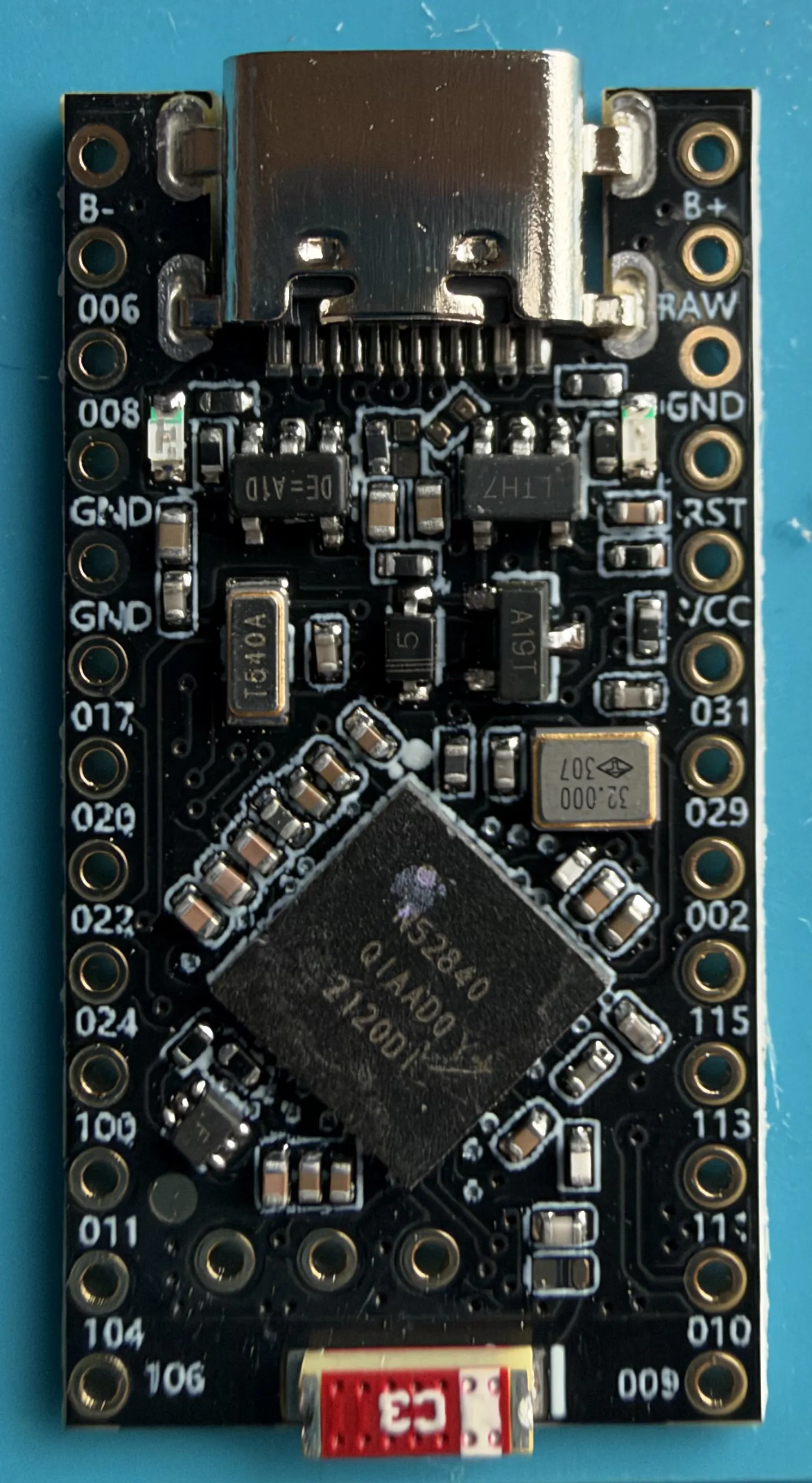
Section titled “MCU (Microcontroller Unit)”The board used for this tracker is the SuperMini (ProMicro) nRF52840
Flashing Firmware
Section titled “Flashing Firmware”The firmware flashing guide has not been created yet
Pre-solder points
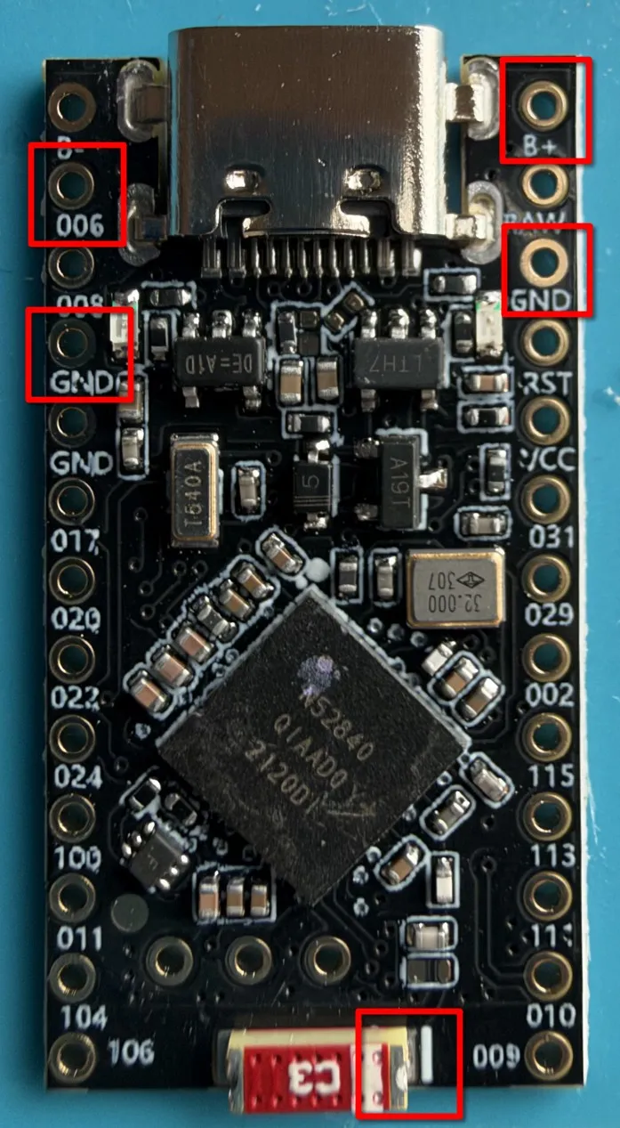
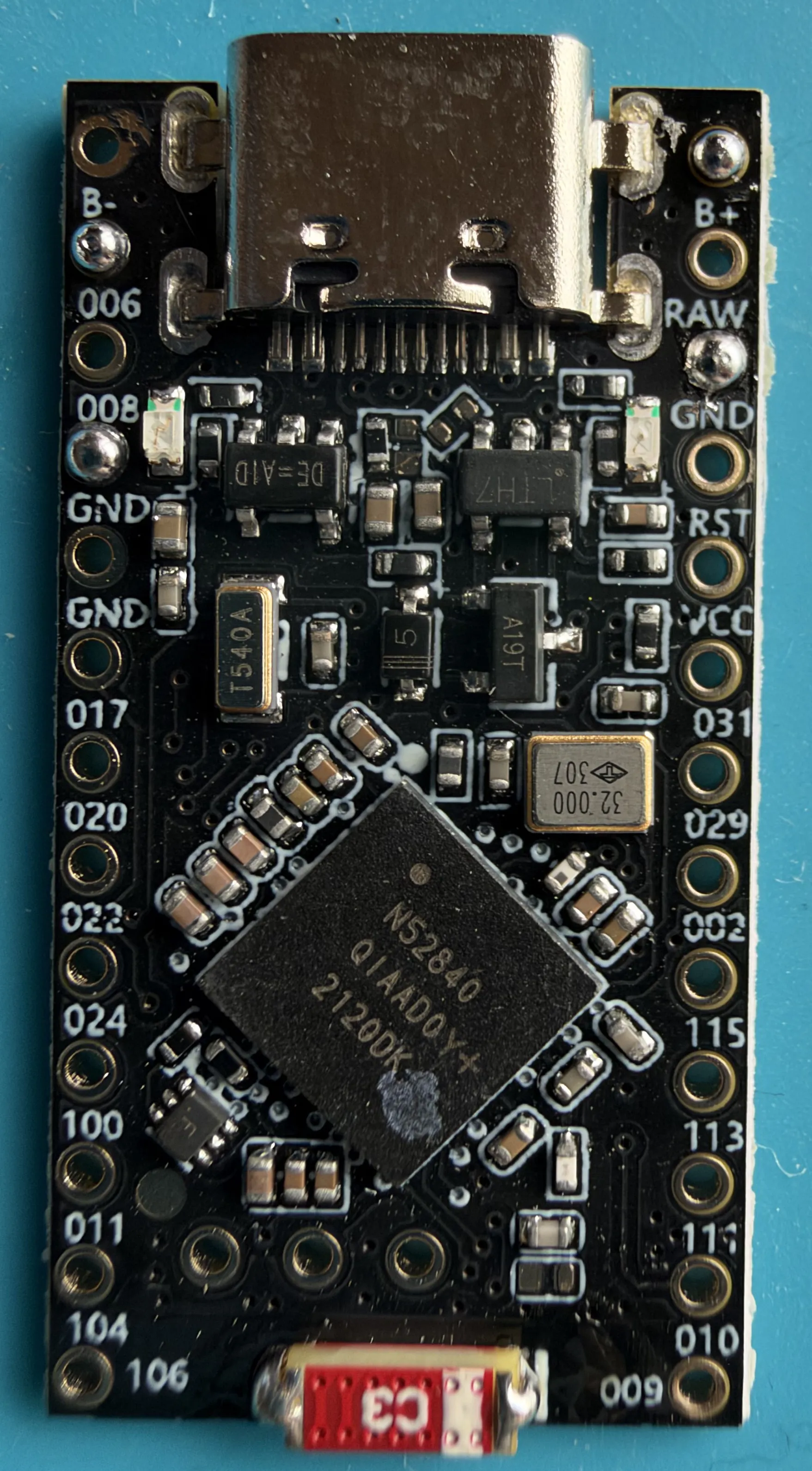
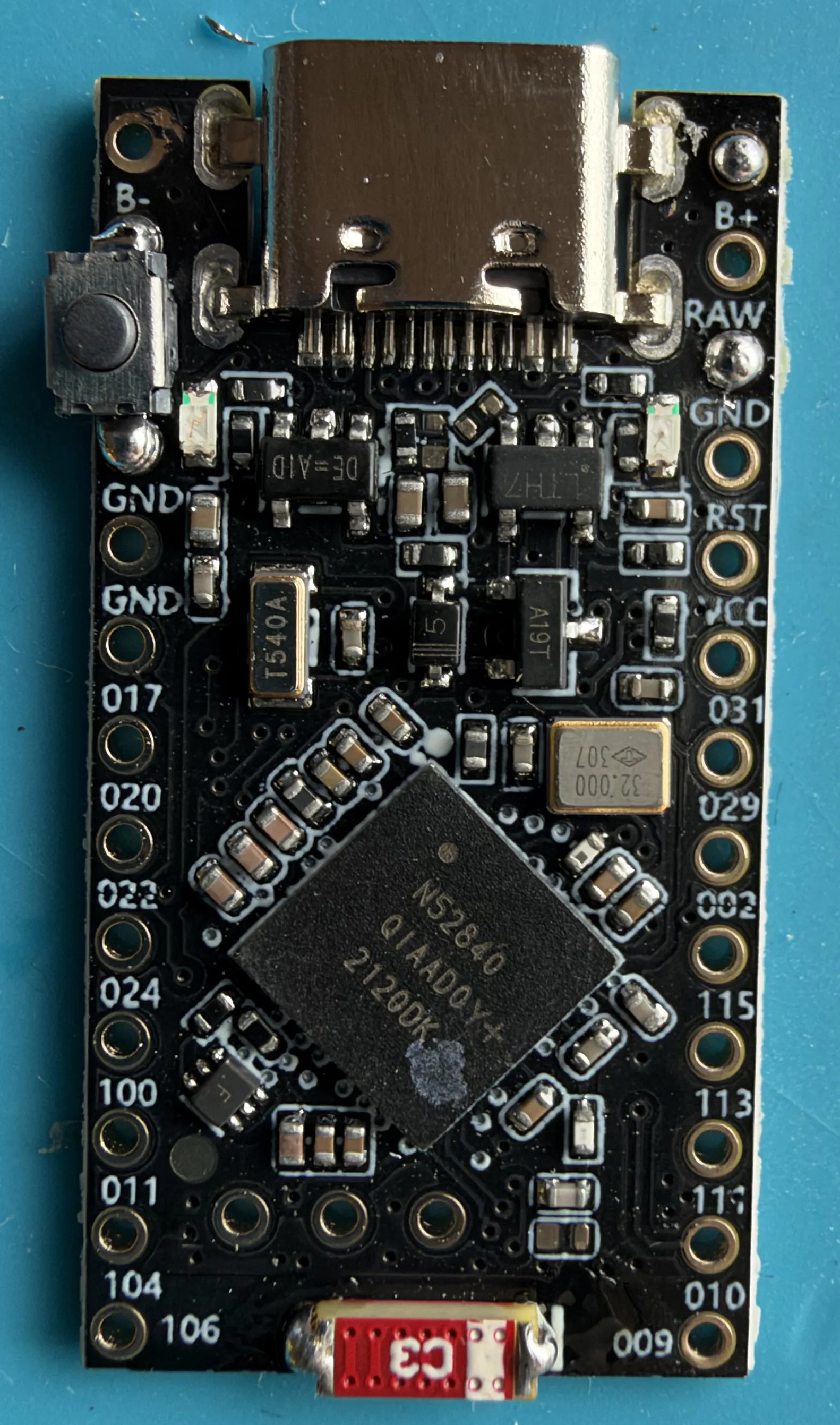
Section titled “Pre-solder points”We are going to pre-solder some points ahead of time on your MCU in order to make things easier for later steps.
These points are:
- B+ & GND - Battery terminals
- 006 & GND - Button
- C3 - Wire mod (For improved signal)
 |  |
Solder the button
Section titled “Solder the button”Connect your button to the 006 and GND pins that you soldered in the previous step you can do this by the button ontop of the solder using a pair of pliers then heating the pins and the solder to push the button into the solder ball:
Combining
Section titled “Combining”First side
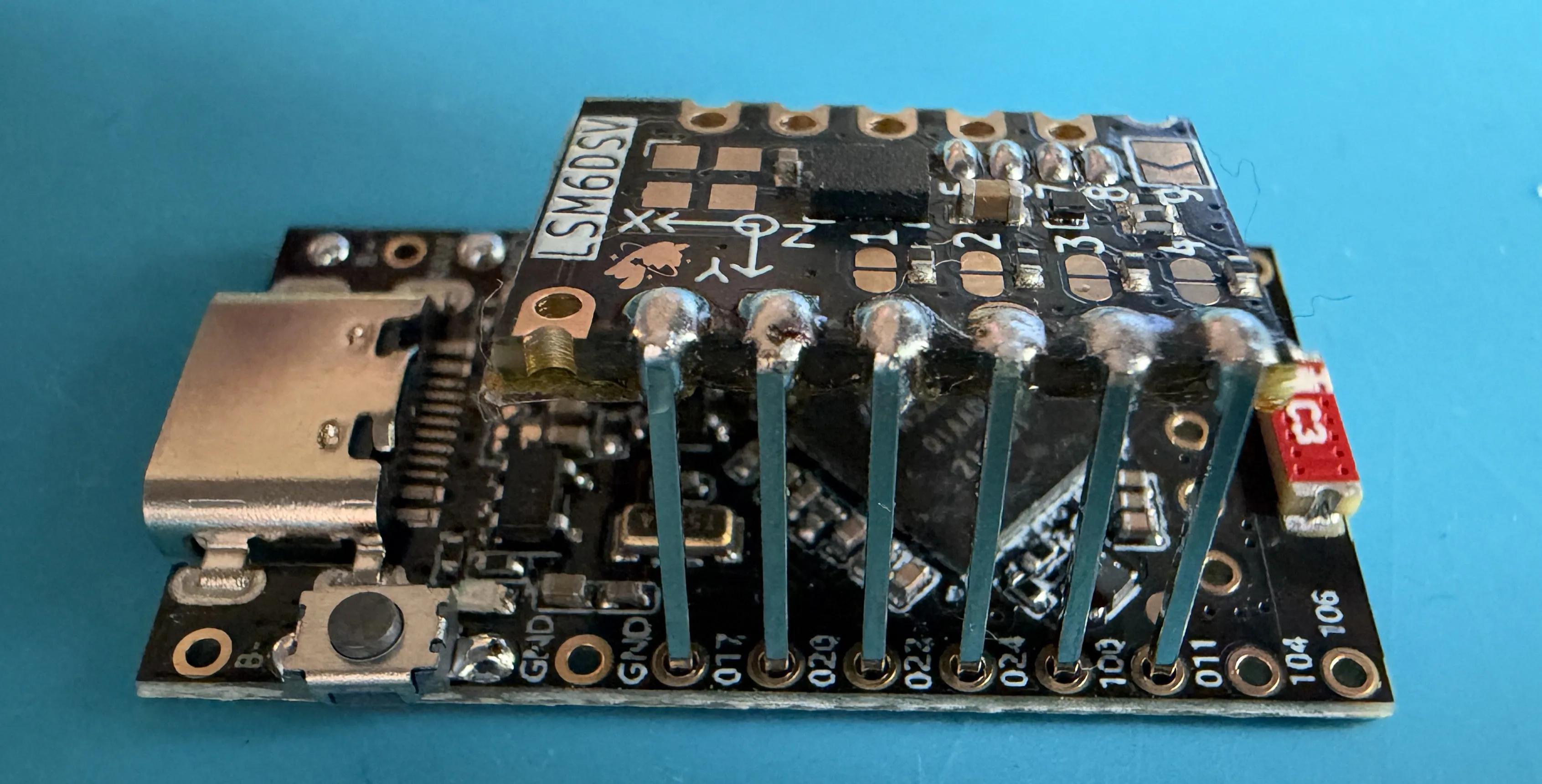
Section titled “First side”You can now combine the IMU and the MCU. Place the IMU on top of your MCU placing its pins through holes 017 through to 100, the LSM6DSV label should be facing in the same direction as the USB-C port like below:
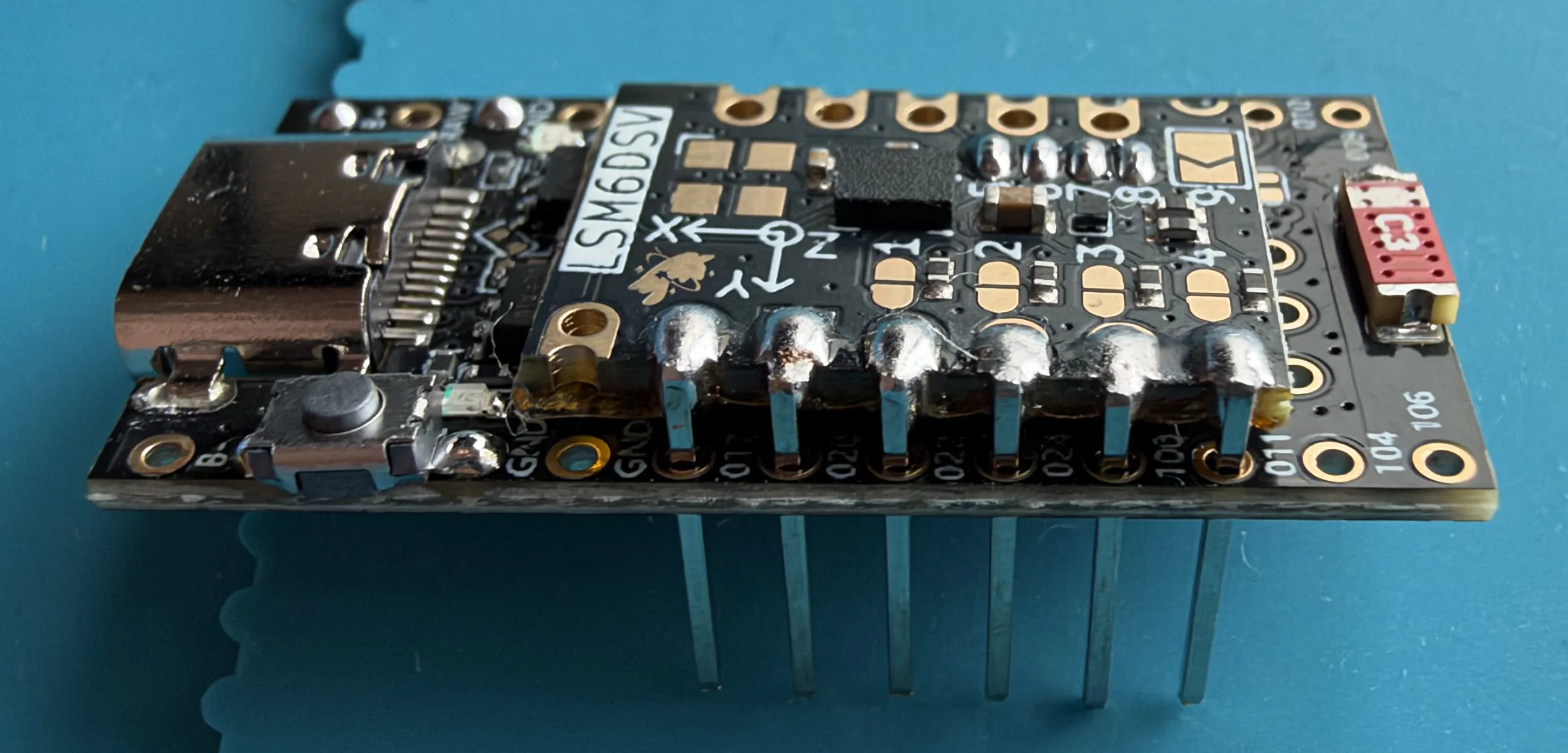
Push your IMU through the MCU holes until it is fit snug against the MCU:
Now you can flip the board over to the bottom:
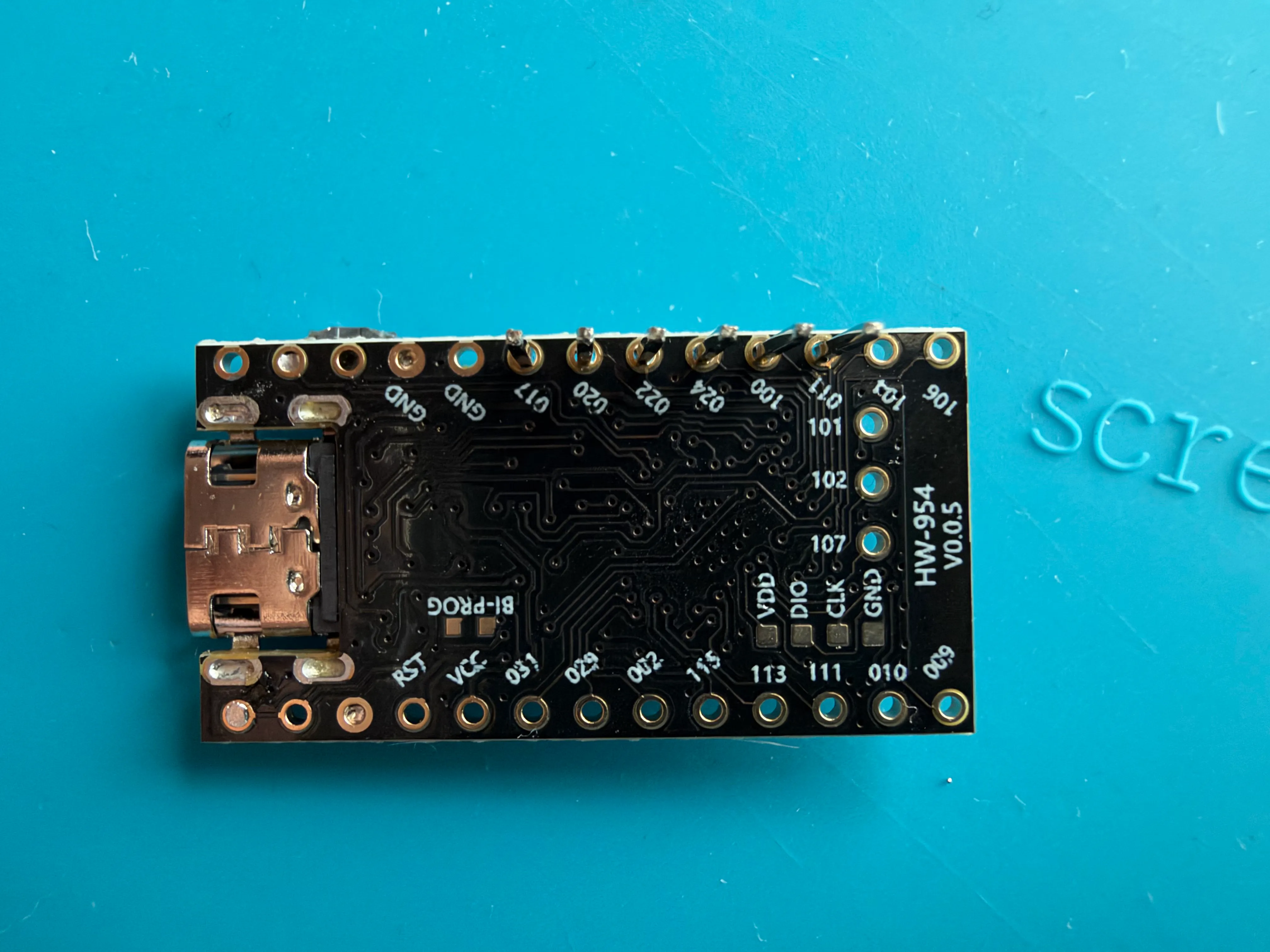
And snip off the pins until they are flush with the bottom of the MCU:
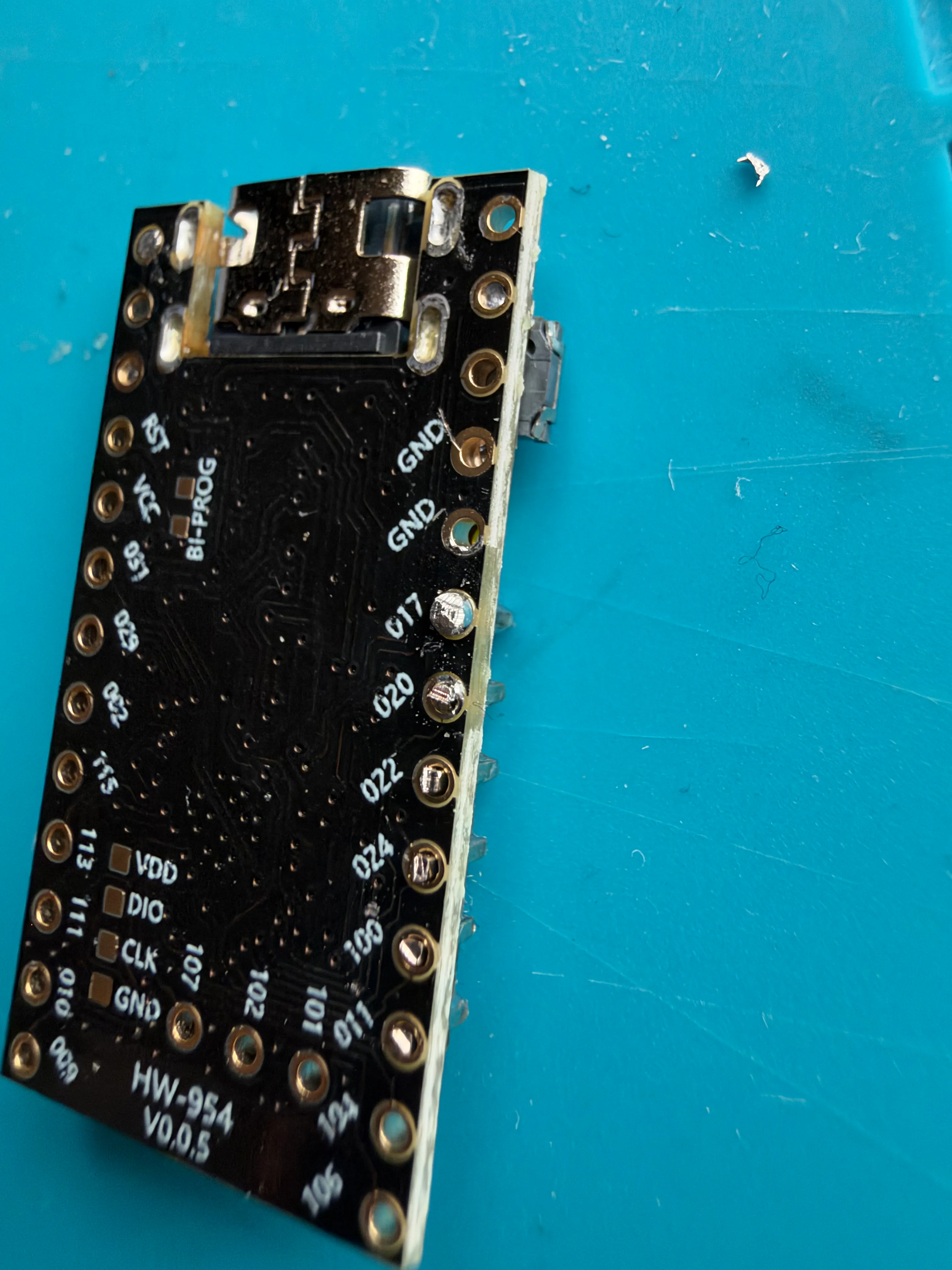
Solder the snipped pins to the underside of the MCU:
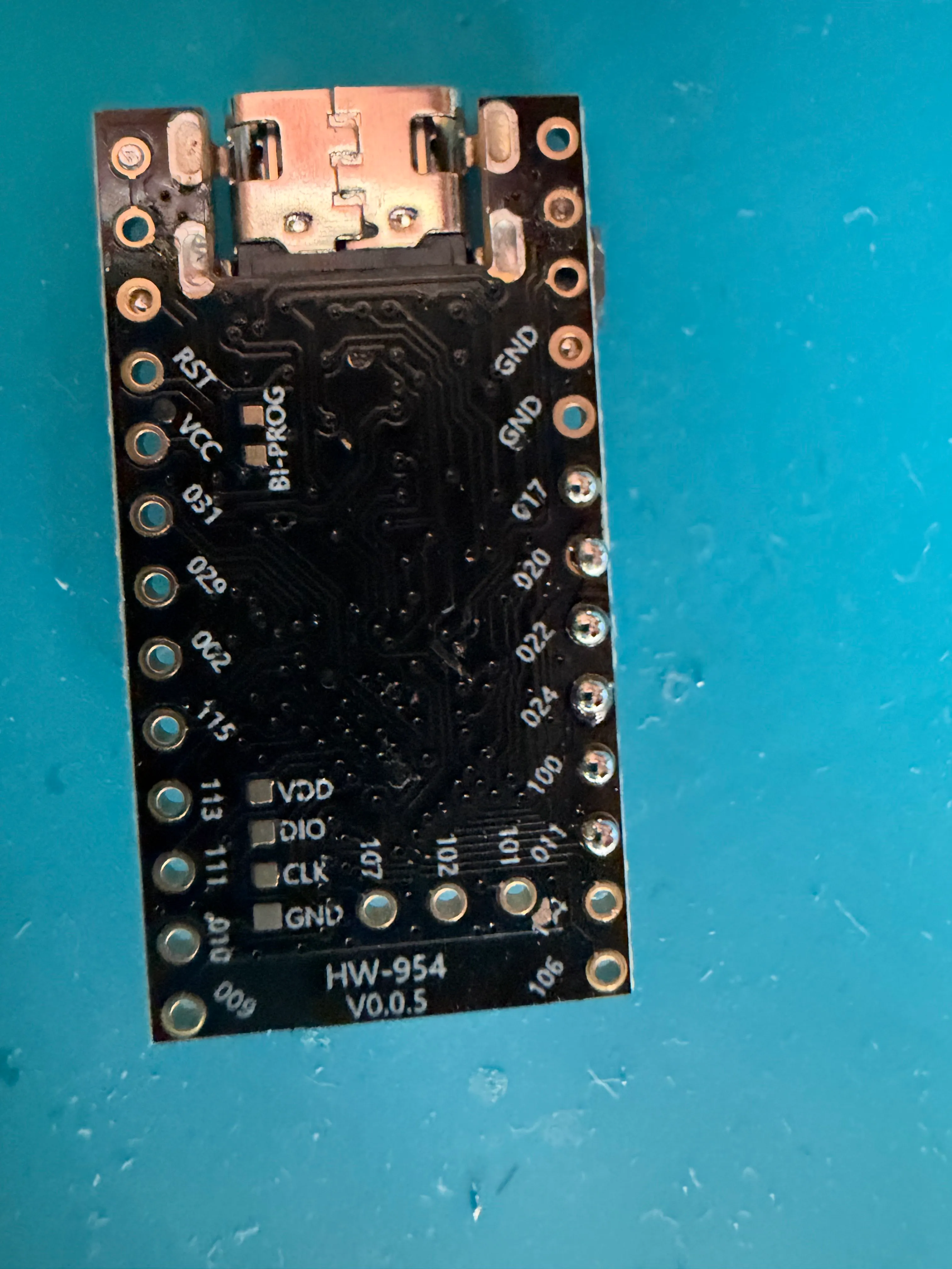
Your tracker should now look like this:
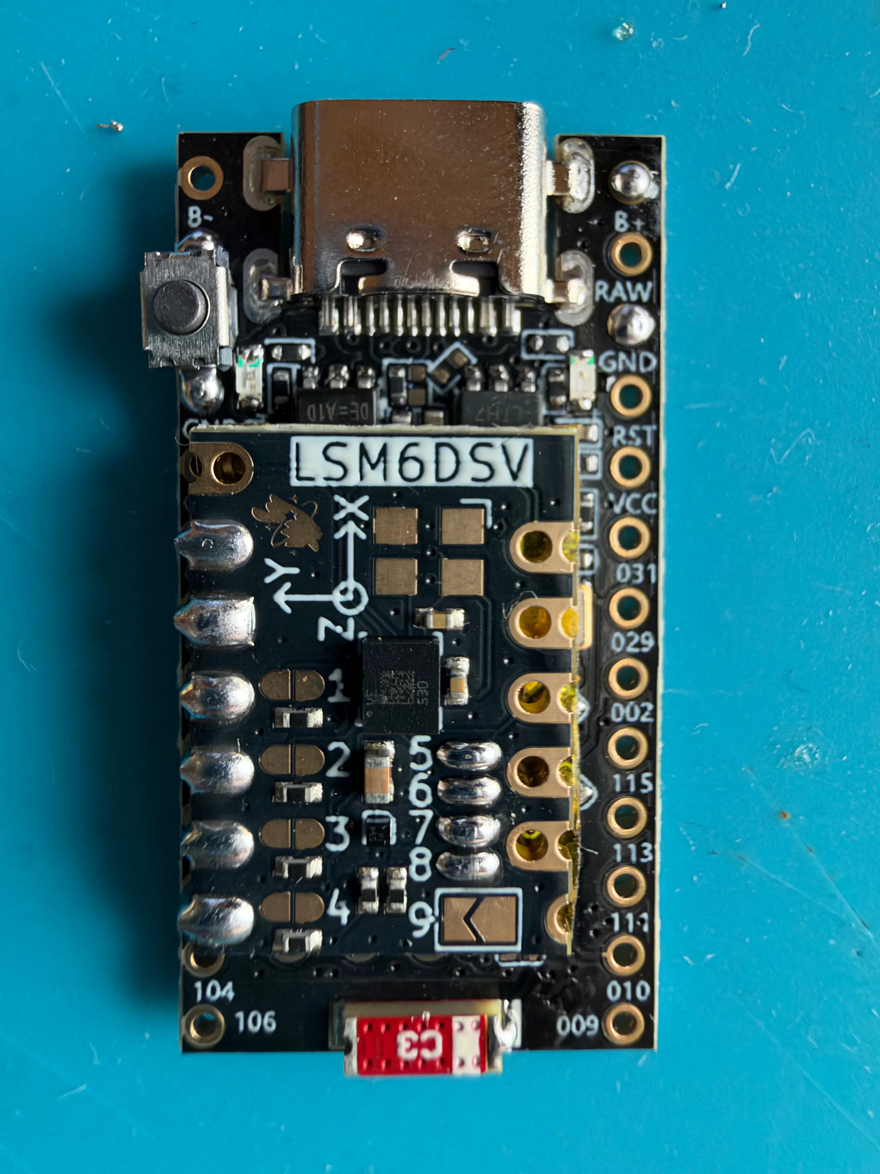
Second side
Section titled “Second side”Next we need to connect 002 on the MCU to the corresponding pin on the IMU
Bending the spare pin
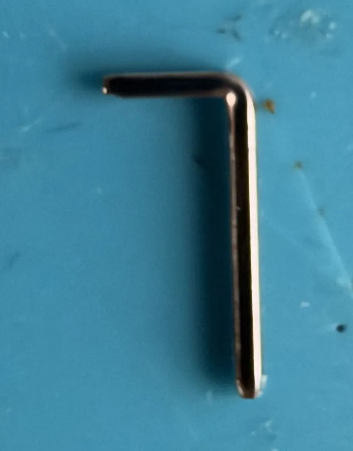
Section titled “Bending the spare pin”Take the spare 1 pin from the pins that we split previously and create a 90deg bend at the top and remove the plastic from the bottom like so:
Solder the pin
Section titled “Solder the pin”Insert the pin through hole 002 on the MCU ensuring the bent portion connects with the IMU like so:
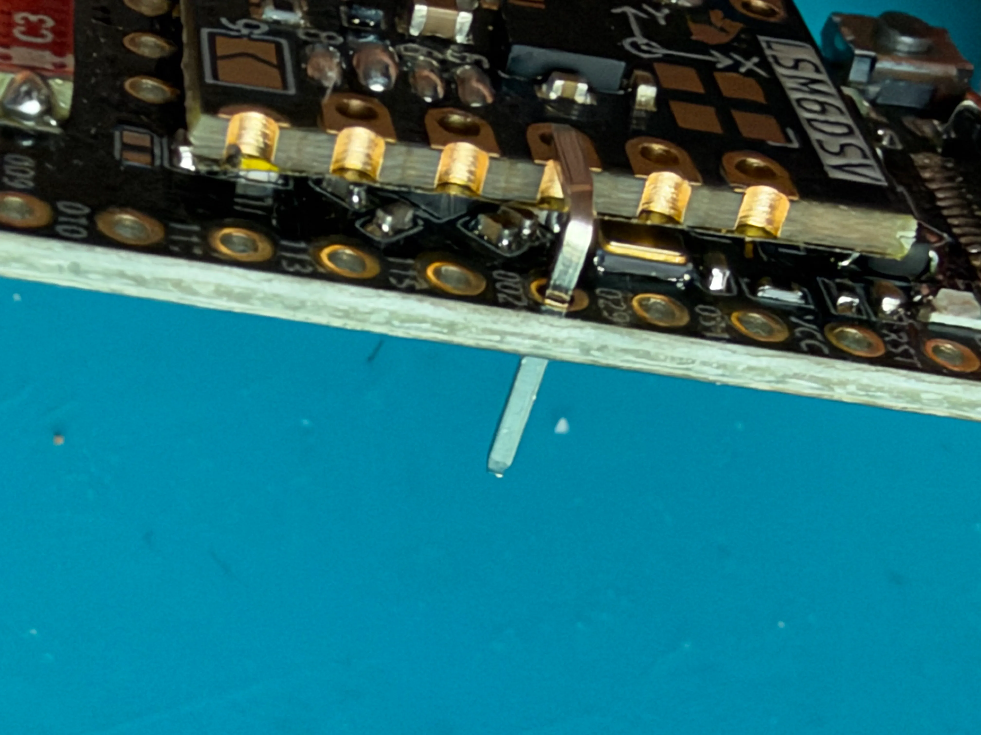
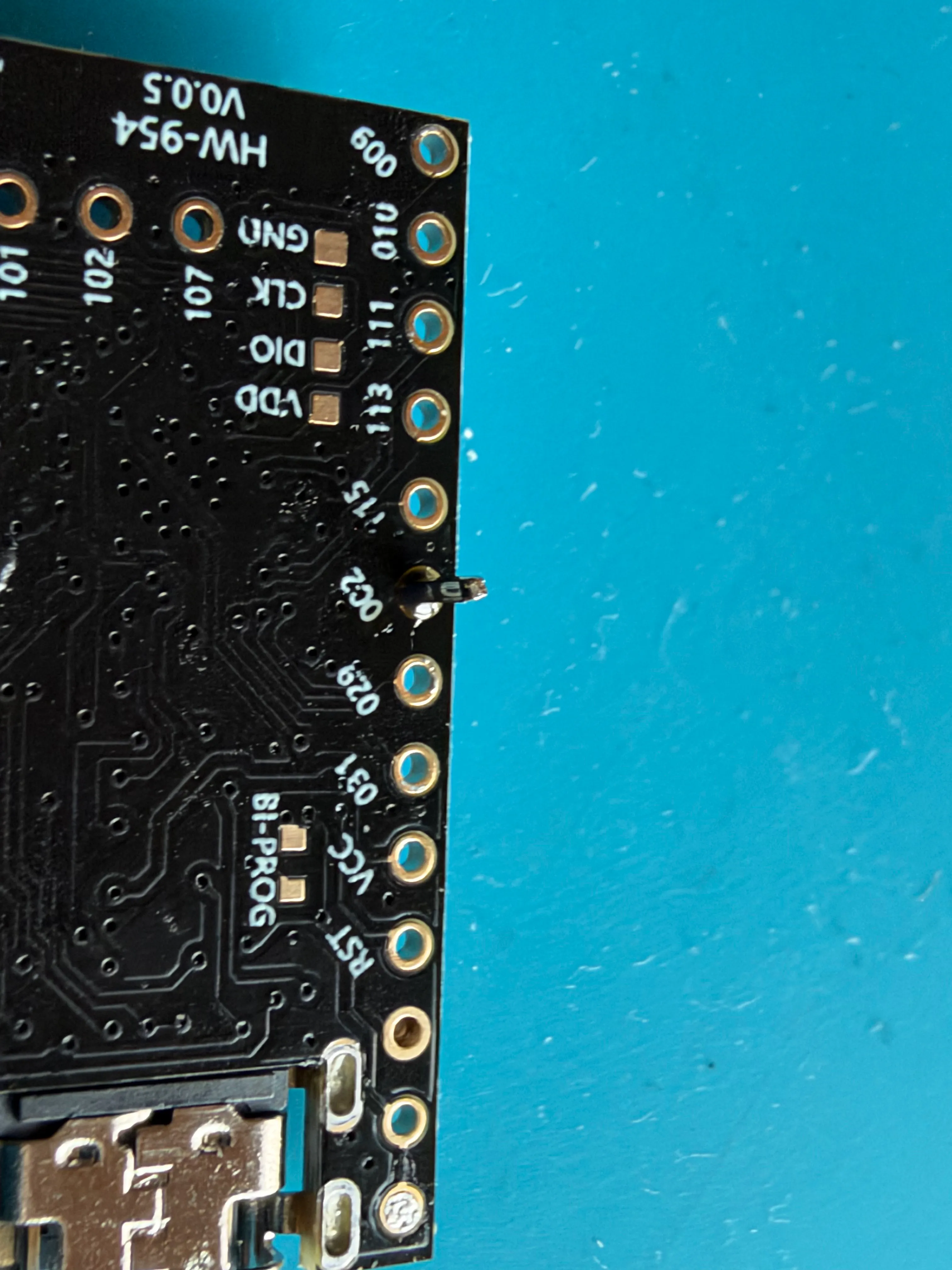
Then flip the tracker over and solder the pin from underneath the board, ensure the pin doesn’t rotate while you are flipping it or soldering it:
Once you’ve soldered the bottom solder the top portion to the IMU
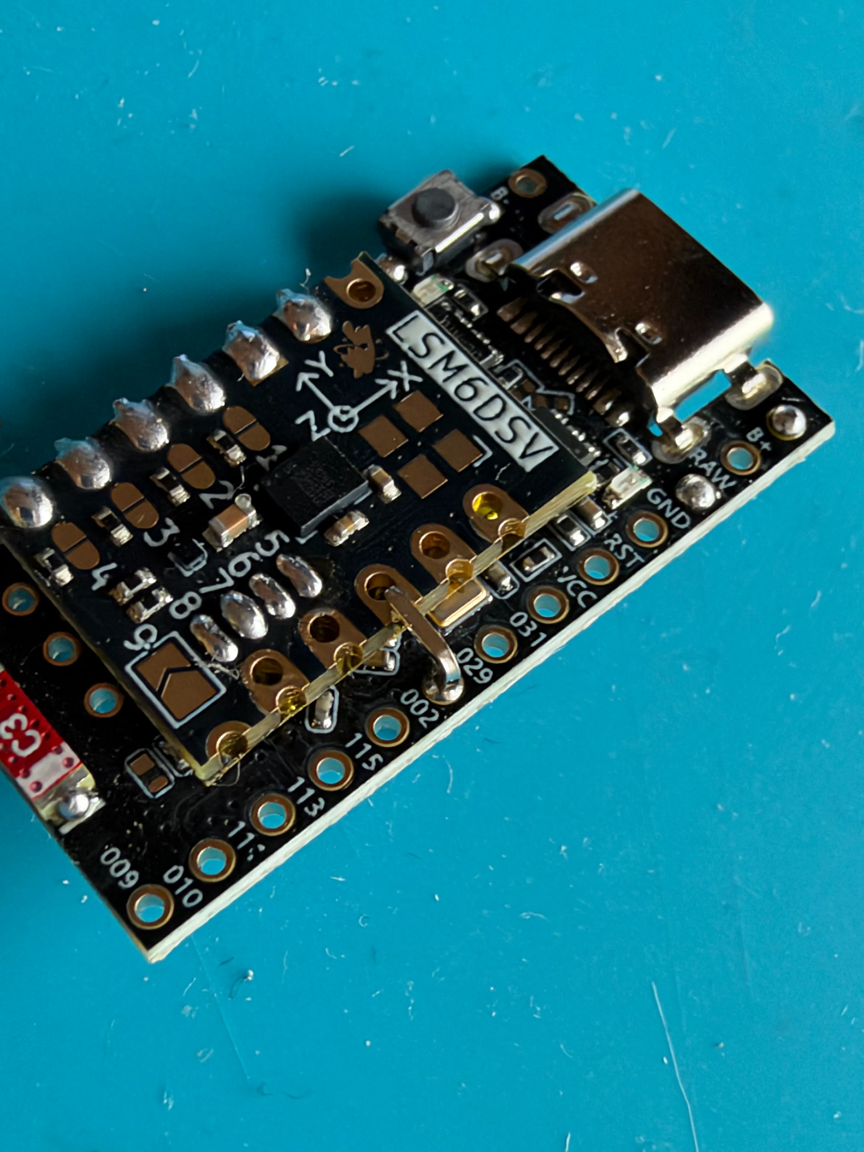 | 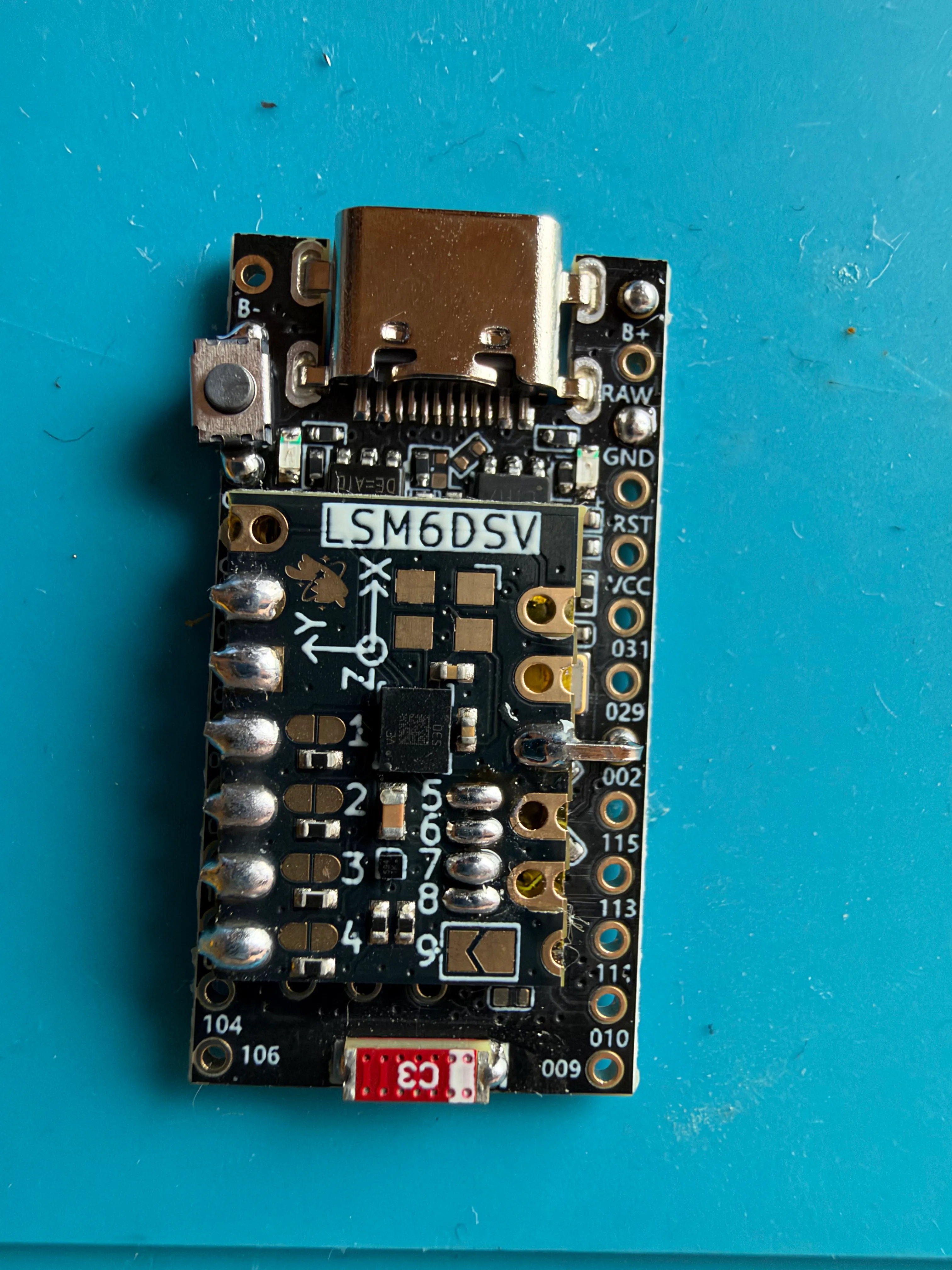 |
Make sure you snip off the rest of the pin at the bottom so that its flush to the MCU, you may need to resolder hte bottom after making it flush.
The testing guide has not been created yet, but at this point it would be a good idea to use a serial console with the tracker plugged into your computer to test that the tracker is detecting your IMU and Magnetometer
Wire mod
Section titled “Wire mod”Cutting wire
Section titled “Cutting wire”Next to improve the signal strength of our MCU (“SuperMinis have horrendous signal strength by themselves”) we will cut a piece of wire to act as a antenna.
Cut around 33mm of your wire for however many trackers you need:
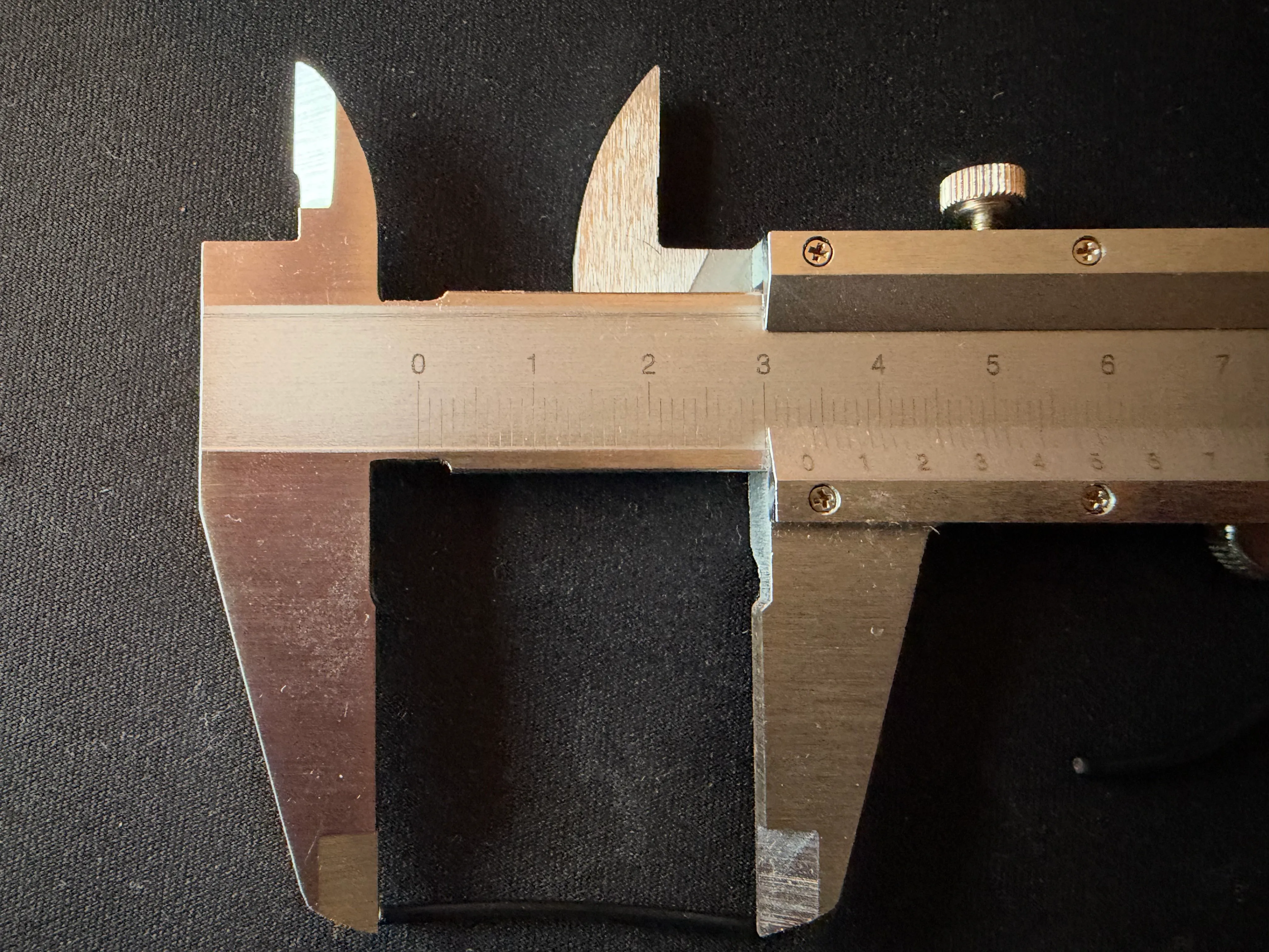
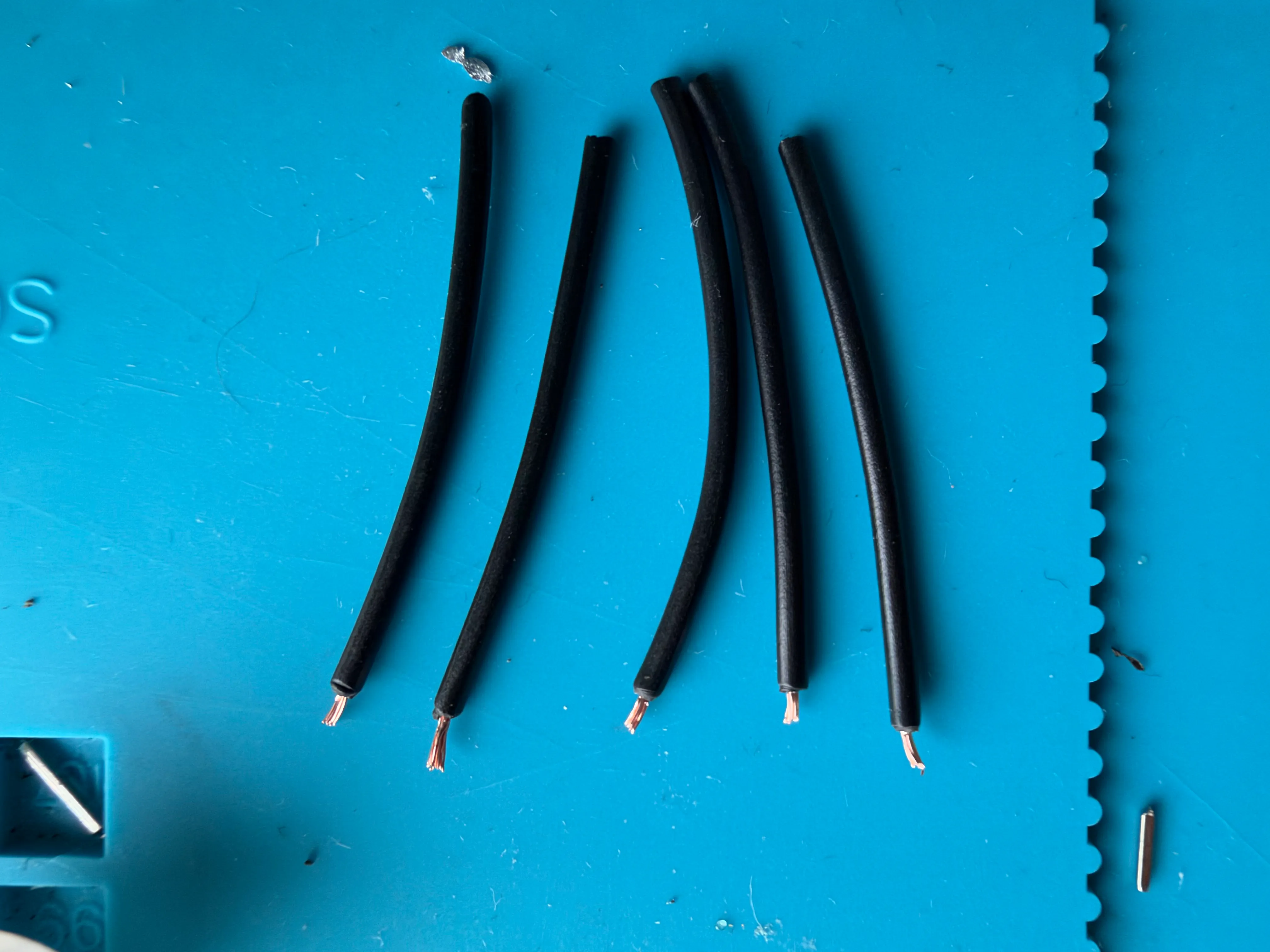
After cutting your wire strip ~1mm of the casing from the end of the wire
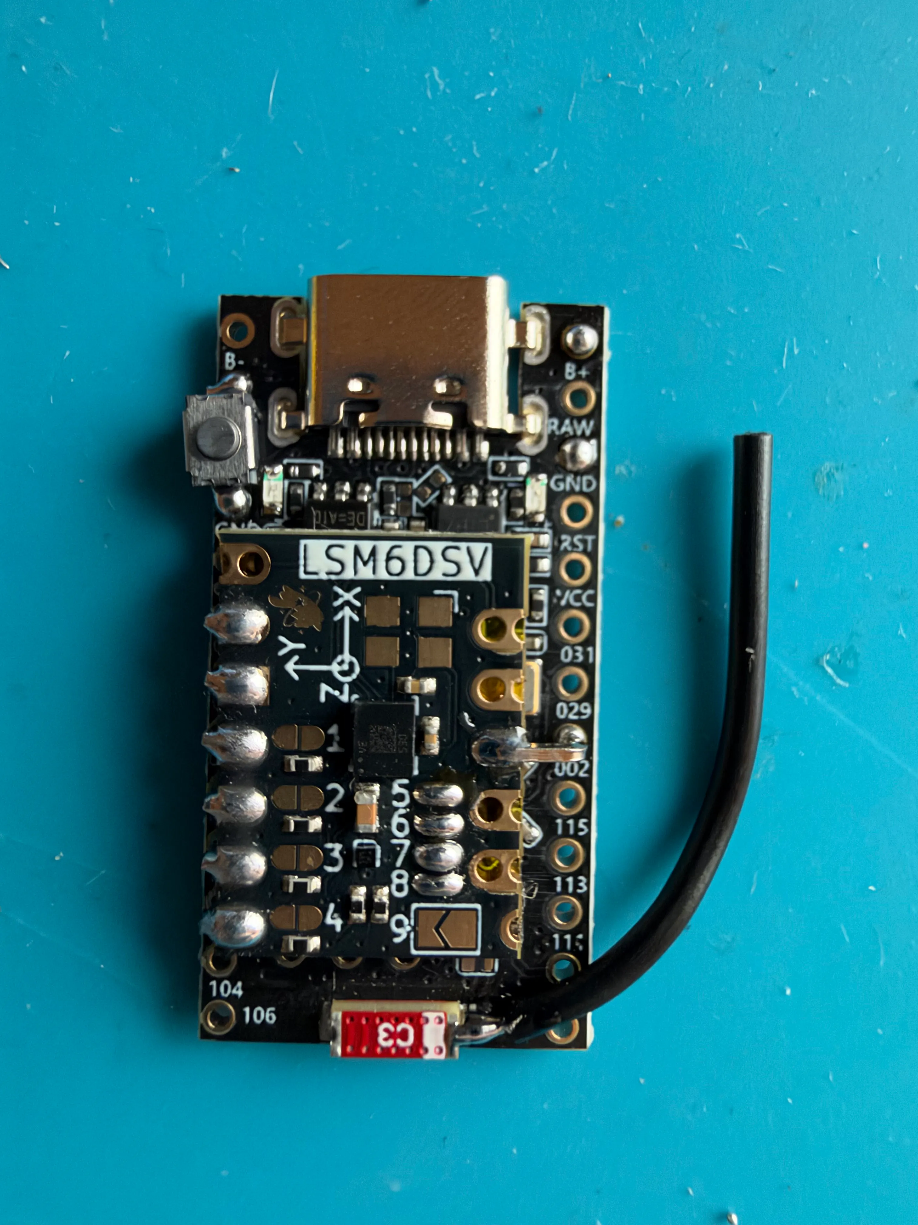
Now you can solder your wire to the MCU in the following spot:
Battery
Section titled “Battery”Now all thats left to solder is your battery:
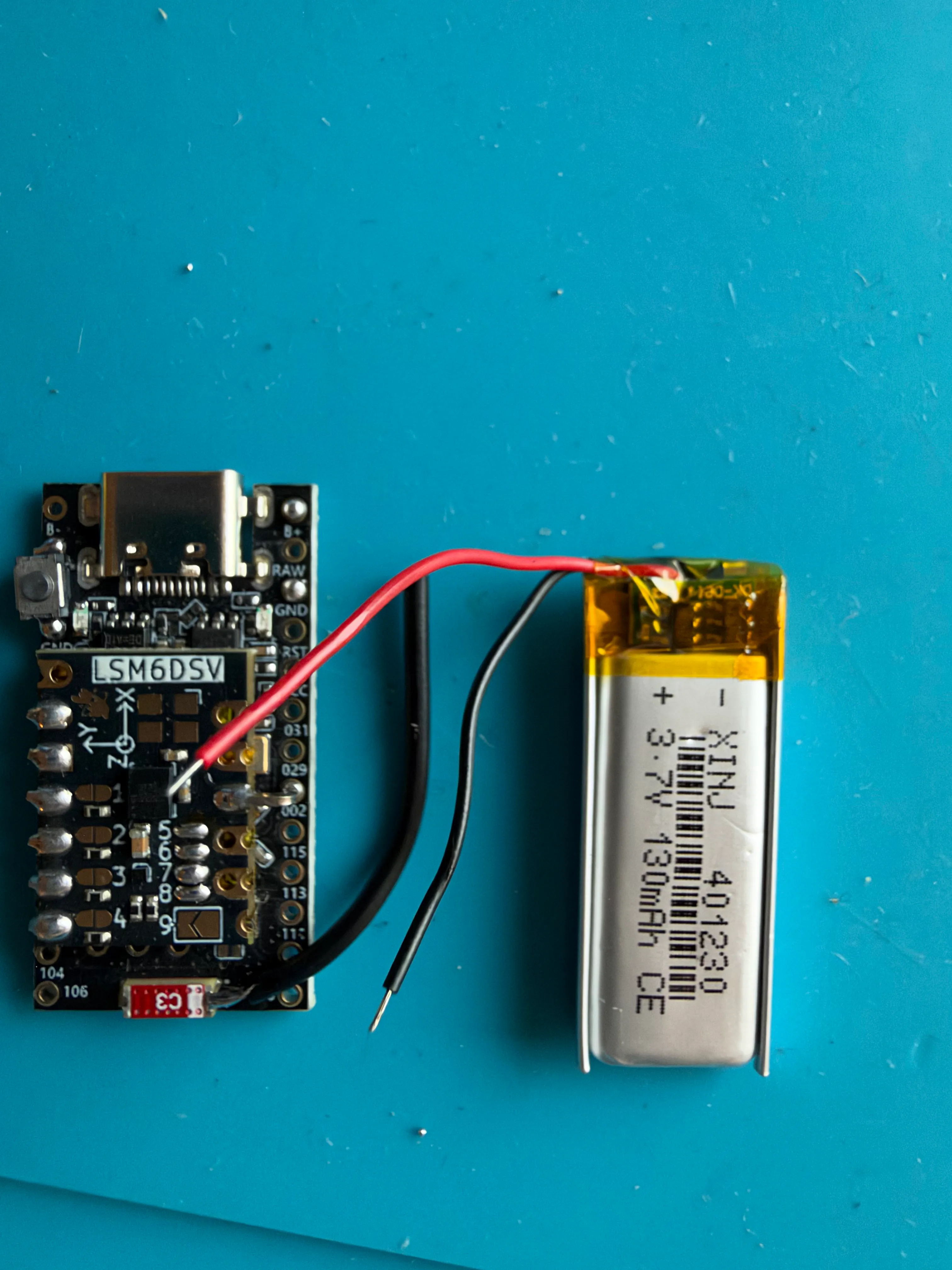
Connect the red wire from your battery to the B+ pin on the MCU that you’ve soldered previously and the black wire form your battery to the GND pin under the B+ like so:
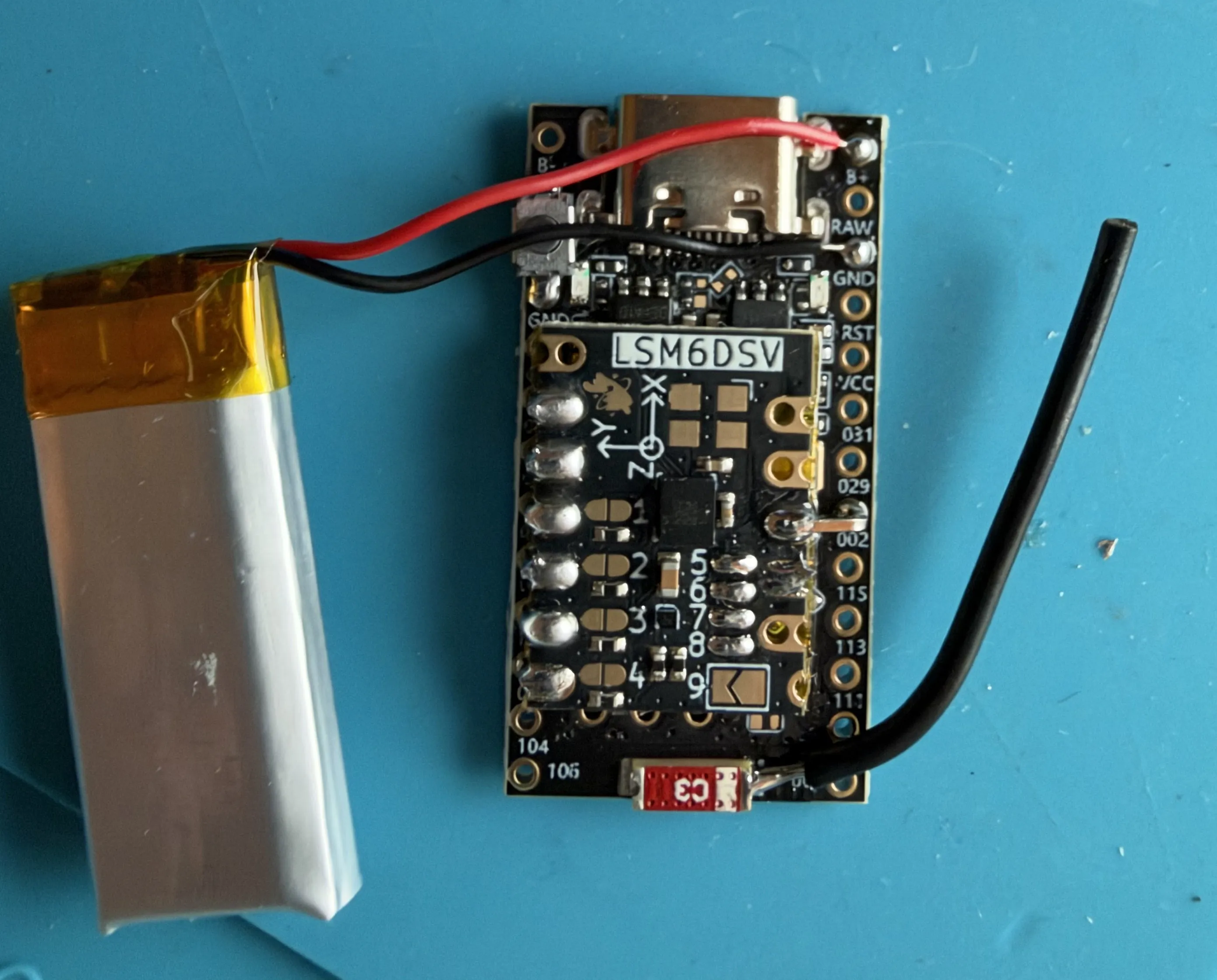
Your tracker is now complete you can stick it into your case now:
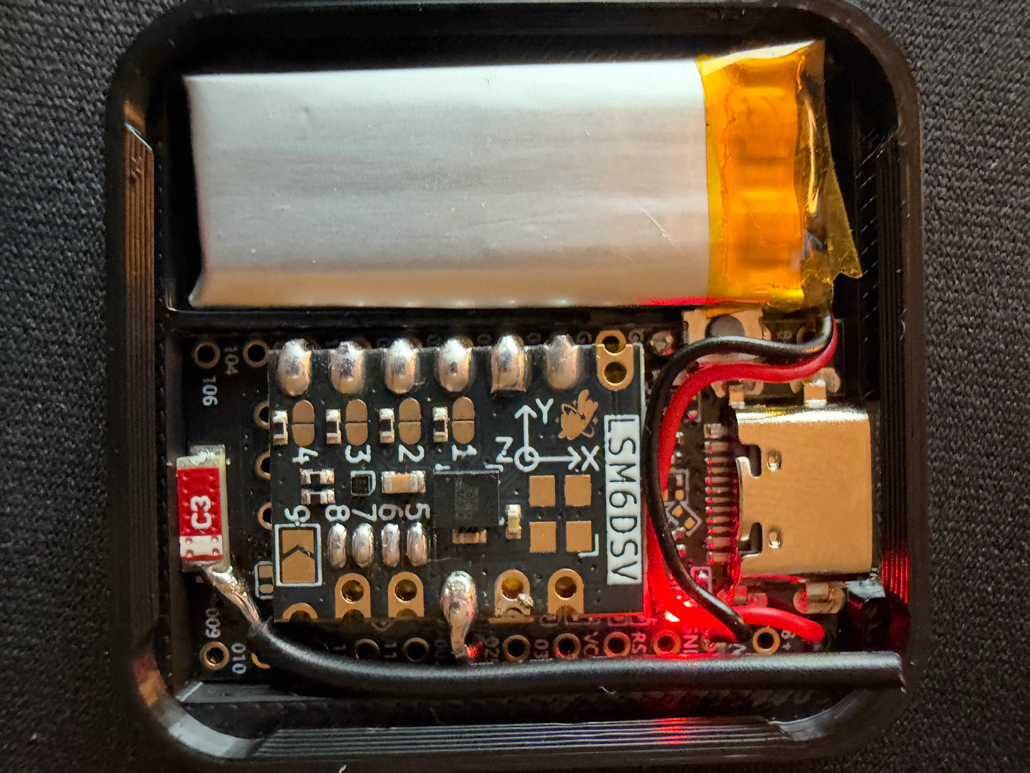
All done
Section titled “All done”Now its time to Pair & Calibrate your trackers